


Photoelectric sensors detect objects and surface changes using variations in optical properties. Each sensor includes a light emitter and a receiver, with most relying on infrared light. In optical proximity sensing, the emitter and receiver are housed in the same unit.
An infrared reflectance sensor, also known as a diffuse sensor, detects changes in reflected light from a target. This variation alters the light received, which is then converted into an electrical signal. Some of these sensors and modules, widely available at electronics retailers, are shown in Fig. 1. The components required to assemble the device are listed in the Bill of Materials table.
POC Video Tutorial

| Bill of Materials | ||
| Components | Description | Quantity |
| Arduino Uno/Nano (Board1) | For uploading code | 1 |
| Analogue reflectance sensor module or (IR and phototransistor pair) | for example, CNY70 or homemade | 1 |
| 330Ω, ¼W resistor | Current limiting | 1 |
| 10KΩ, ¼W resistor | Pull-up resistor | 1 |
| Passive buzzer | For sound | 1 |
| Jumper wire | For connection | As required |
| Two-pin connector | For the power supply | 1 |
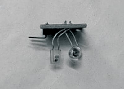
Note: A compact analogue reflectance sensor such as the CNY70 was not used in the Arduino Uno experiments described. Instead, a homemade sensor was assembled using a single infrared LED (IR333C) and a commonly available phototransistor (PT908-7C-F). Fig. 2 shows the homemade reflectance sensor.

For practical applications, the phototransistor output of an analogue infrared reflectance sensor must be connected to a pull-up resistor to form a voltage divider, which yields an analogue voltage that ranges between GND and Vcc. With strong reflectance, the output voltage tends towards GND; with weak reflectance, it tends towards Vcc. The resistor wired in series with the infrared LED sets the operating current to a safe value. This configuration can be tested using an Arduino Uno. Fig. 3 shows the internal circuit of an infrared reflectance sensor.
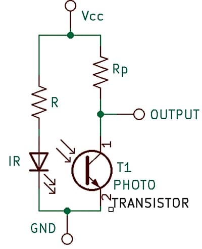
Circuit and Working
