


Advances in embedded systems and sensors have enabled efficient, intelligent surveillance solutions that improve safety and control in transportation and automation applications. The system presented here offers a low-cost, efficient method for real-time vehicle speed monitoring using a microcontroller.
When no object or car is detected, the display shows ‘No Car Detected.’ Once an object is sensed, the system switches to speed measurement mode. Speed is calculated by measuring the time taken for a vehicle to travel between two infrared (IR) sensors placed a fixed distance apart. The timer starts when the vehicle crosses the first sensor and stops when it crosses the second.
POC Video Tutorial
This real-time feedback allows authorities or operators to verify whether vehicles are travelling within safe limits. If the calculated speed exceeds a preset threshold (for example, 60km/hr), the buzzer sounds to indicate overspeed. The system is therefore well-suited for areas requiring strict speed control, such as school zones, hospital campuses, and parking areas.

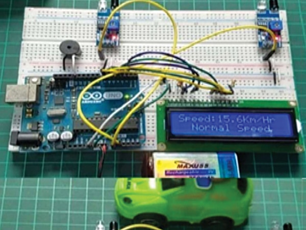
Fig. 1 shows the prototype assembled on a breadboard. The components required to build the system are listed in the Bill of Materials table.
| Bill Of Materials | |
| Components | Quantity |
| Arduino Uno R3 (MOD1) | 1 |
| Buzzer (B1) | 1 |
| IR sensor (S1, S2) | 2 |
| 16×2 LCD display (LCD1) | 1 |
| 1k potmeter (POT1) | 1 |
| Jumper wires | As required |
Block diagram
Fig. 2 shows the system block diagram. It consists of two IR sensors, an Arduino board, an LCD display, and a buzzer that together perform object detection and speed monitoring. The sensors, placed at a fixed distance, detect the movement of an object as it passes between them. The Arduino serves as the main controller, receiving signals from both sensors and calculating speed from the time difference between detections.
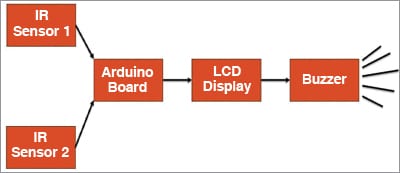
The calculated speed and detection status are displayed on the LCD in real time. If the speed exceeds the predefined limit, the buzzer is activated to provide an audible warning, thereby enhancing road safety.
Circuit and working
Fig. 3 shows the circuit diagram of the smart speed monitoring system. It is built around an Arduino Uno R3 board (MOD1), IR sensors (S1, S2), an LCD display (LCD1), a buzzer (B1), and supporting components. The buzzer sound indicates overspeed.

