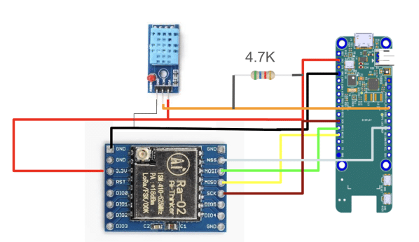
This project implements an intelligent IoT gateway that bridges long-range wireless sensor networks with a modern web dashboard and AI-driven analytics. Using an SX1278 transceiver managed by RadioLib, the receiver captures incoming LoRa packets on the 433 MHz band, calculates signal quality metrics (RSSI and SNR), and structures the valid data into a JSON payload
Video Tutorial:
Components List:
| Component | Quantity |
| Arduino UNO Q (ABX00087) | 1 |
| SX1278 | 3 |
| ESP32 dev module | 1 |
| MAX32672 FTHR evaluation kit | 1 |
| DHT11 sensor | 1 |
| OLED display | 1 |
| 3.7V lithium-ion battery | 1 |
Project Explanation:
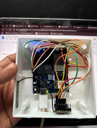
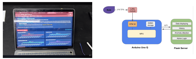
The system utilises the Arduino RouterBridge framework to expose an RPC endpoint (getLatestPayload), allowing a companion router or host system to fetch live sensor data instantly. This data is fed directly into a responsive web dashboard, which visualises real-time telemetry, environmental trends, and node health. Furthermore, an integrated AI component analyses the incoming data streams to detect anomalies, predict sensor failures, or provide automated insights. By combining long-range RF communication, remote procedure calls, real-time web visualisation, and smart AI analytics, the project delivers a comprehensive, end-to-end intelligent monitoring solution.
Code Explanation and Configuration:
Coding Explanation and Configuration First and foremost, we need to install the necessary library to the Arduino IDE. To do this, navigate to the Sketch menu and click on “Manage Library.” Next, search for the library name and click on the “Install” button. The library required for this project are the Radiolib library by Jan Gromes.
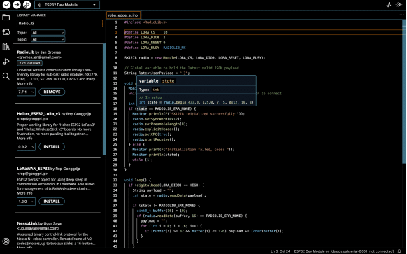
Here is the step-by-step technical breakdown of your RadioLib-based LoRa receiver and acknowledgement code:
Step 1: Library Inclusion & Hardware Pin Definitions
- Line 1: #include <RadioLib.h> imports the universal wireless communication library used to control the LoRa radio module.
- Lines 3–6: Define the physical SPI interface and control pins connected to the SX1278 module:
- LORA_CS (10): Chip Select pin for SPI communication.
- LORA_DIO0 (2): Digital I/O pin 0 used to signal hardware interrupts (e.g., packet received).
- LORA_RESET (9): Hardware pin used to hard-reset the radio transceiver.
- LORA_BUSY (RADIOLIB_NC): Set to “Not Connected”, as the SX1278 (unlike the SX1262 series) does not utilise a dedicated BUSY pin.
Step 2: Global Object Initialisation
- Line 8: Instantiates the SX1278 radio object dynamically with the pin mapping defined in Step 1.
- Line 11: Declares a global string latestJsonPayload initialised to {}. This stores the most recent valid packet, making it accessible to higher-level system components (such as the Linux side on the Arduino UNO Q via RPC).
Step 3: Device Setup & Hardware Initialization (setup())
- Lines 14–15: Initializes Monitor.begin(9600) (the serial debugging interface for Arduino App Lab / UNO Q ecosystem) with a 3-second timeout protection loop so the board boots up even without a live serial terminal attached.
- Line 17: Calls radio.begin(…) to configure the core RF parameters:
- Carrier Frequency: 433.0 MHz
- Bandwidth: 125.0 kHz
- Spreading Factor: SF7
- Coding Rate: 4/5
- Sync Word: 0x12
- Transmit Power: 10 dBm
- Preamble Length: 8 symbols
- Lines 18–24: If initialisation returns RADIOLIB_ERR_NONE (success):
- Sets explicit packet headers and enables CRC hardware error checking to automatically drop corrupted frames.
- Calls radio.startReceive() to place the module into continuous asynchronous listening mode.
- Sets explicit packet headers and enables CRC hardware error checking to automatically drop corrupted frames.
- Lines 25–28: If initialisation fails, prints the error code and traps execution inside a while(1) halt loop
Step 4: Packet Detection Loop (loop())
Line 32: Checks if (digitalRead(LORA_DIO0) == HIGH). The SX1278 hardware pulls DIO0 HIGH as soon as a valid payload is detected in the air and stored in its internal FIFO buffer
Step 5: Dual-Strategy Payload Extraction
- Lines 33–34: Attempts a standard high-level read: radio.readData(payload).
- Lines 36–45 (Fallback Rescue Logic): If standard extraction fails (e.g., raw string parsing error):
- Creates a raw byte buffer uint8_t buffer[16].
- Attempts to manually read the first 16 bytes of the FIFO buffer.
- Iterates through the raw bytes and filters for printable ASCII characters (ASCII range 32–126), reconstructing the payload manually so data isn’t lost.
Step 6: Signal Health Metrics Calculation
- Lines 47–48: Queries the SX1278 registers for link diagnostics:
- getRSSI(): Measures the Received Signal Strength Indicator (signal power level in dBm).
- getSNR(): Calculates the Signal-to-Noise Ratio (signal clarity in dB)
Step 7: Filtering, JSON Packaging, and Acking
- Line 50: Evaluates packet validity. A payload is processed only if it is non-empty and has a clear signal clarity threshold (snr > -12.0 dB).
- Lines 51–57: Formats the payload, RSSI, and SNR into a standard JSON string format (e.g., {“payload”:”hello”,”rssi”:-45.00,”snr”:8.50}) and updates the global latestJsonPayload variable.
- Line 60: Outputs the formatted JSON string to Monitor for debugging.
- Lines 63–66 (Acknowledgement Transmission):
- Waits 50 ms to allow the sending node to switch into listening mode.
- Executes radio.transmit(“ok”) to send an “ok” ACK back to the node.
- Restores explicit headers and CRC flags for the transceiver.
Step 8: Returning to Listening State
- Line 69: Re-executes radio.startReceive() to return the module to passive reception mode after handling the ACK.
- Line 71: delay(20) provides a small polling pause to stabilise execution and reduce CPU load during idle loops.
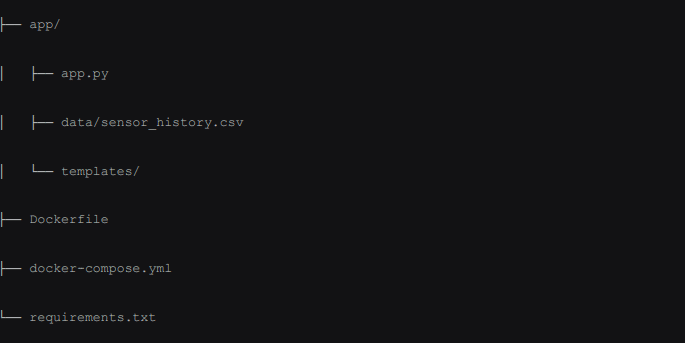
1. Directory Structure
2. Project Architecture Overview
This project implements an edge-intelligent LoRa telemetry dashboard. The architecture consists of four distinct operational layers:
- TCP Socket Ingestion Layer: Runs a continuous background thread (tcp_bridge_reader_thread) that listens on TCP port 7500 (127.0.0.1) for incoming JSON payloads pushed by the LoRa hardware packet forwarder.
- Dynamic Trend & Machine Learning Engine (DynamicTrendMLModel):
- Payload Parsing: Uses regular expressions to classify telemetry into categories (Temp & Humidity, Water Level Probe, Counter/Heartbeat).
- Exponentially Weighted Moving Average (EWMA): Tracks baseline environmental changes across time using an alpha factor ($\alpha = 0.15$).
- Velocity Delta Tracking ($\Delta / \Delta t$): Computes rate-of-change spikes per minute across moving standard deviation thresholds ($3\sigma$).
- Isolation Forest Model: Uses Scikit-Learn to detect non-linear multi-dimensional anomalies across Temperature, Humidity, and RSSI space.
- Data Persistence: Automatically initialises and appends structured records into data/sensor_history.csv. 4. Flask Web Presentation & PDF Reporting Layer: Serves dynamic user interfaces using Chart.js for real-time visualisation and ReportLab for automated executive PDF audit reports.
3. Code Breakdown & Technical Explanation
3.1 Backend Application (app.py)
- Imports & Configuration: Imports standard modules (socket, threading, re, csv) alongside numerical stack tools (pandas, numpy, sklearn). Standardises Matplotlib execution to the non-interactive ‘Agg’ backend for server compatibility.
- init_csv() Function: Validates the target directory and populates sensor_history.csv with standardized headers (timestamp, raw_payload, data_type, parsed_json, rssi, snr, is_anomaly, anomaly_reason).
- DynamicTrendMLModel Class:
- fit_model(): Fits an IsolationForest model dynamically whenever $\ge 15$ feature samples are recorded.
- classify_and_parse(): Extracts physical parameters via regular expression matching.
- detect_anomaly(): Validates readings using velocity deviation, absolute hard bounds ($>55^\circ\text{C}$ or $<-10^\circ\text{C}$), empty tank conditions, and Isolation Forest scoring.
- tcp_bridge_reader_thread(): Executes inside a daemon thread, continuously parsing newline-delimited JSON objects sent over socket port 7500 and appending extracted metadata to storage.
- download_report() Route: Compiles recent telemetry data, builds four embedded line chart streams in memory via BytesIO, structures styled detail tables, and returns an auto-generated PDF document.
3.2 Web Interface (templates/)
- login.html: Enforces basic authentication (admin / admin123) using Flask sessions and styled with Bootstrap 5.
- index.html: Polls /api/data every 2000 milliseconds, presenting real-time card metrics and a dynamic 20-sample line graph.
- history.html: Fetches /api/history_all to populate an audit table, applying specific CSS classes (anomaly-row) to highlight anomalous frames in red.
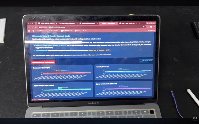
- analytics.html: Integrates Chart.js, hammerjs, and chartjs-plugin-zoom to supply horizontal panning and zoom features across historical temperature, humidity, RSSI, and SNR streams.
Making:
Connection Explanation
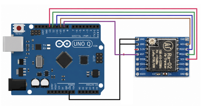
Here is the complete connection breakdown for interfacing the Ai-Thinker RA-02 LoRa Module with the Arduino UNO Q as shown in your circuit diagram.
Pin Mapping Table:
| Arduino UNO Q Pin Ra-02 LoRa | Module | Pin | Wire Colour Function / Interface |
| GND | GND | Black | Ground Reference (Shared across pins) |
| Pin 9 | RST | Purple | Module Hardware Reset Line |
| Pin 10 | NSS (CS) | Brown | SPI Chip Select / Slave Select |
| Pin 11 | MOSI | Blue | SPI Master Out Slave In |
| Pin 12 | MISO | Green | SPI Master In Slave Out |
| Pin 13 | SCK | Pink / Red | SPI Serial Clock |
Detailed Connection Breakdown
Power & Ground Connections:
- Common Ground (GND): The GND pin on the Arduino’s power header connects via the black wire to the ground pins on the Ra-02 module to establish a common electrical reference.
- Operating Voltage Note: The Ra-02 module operates strictly on 3.3V logic and power. (Ensure your hardware configuration supplies 3.3V power to the 3.3V header pin on the module).
SPI Communication Bus:
- SCK (Pin 13 – SCK): Connected via the pink/red wire. Transmits the clock signal generated by the Arduino to synchronise data transmission.
- MISO (Pin 12 – MISO): Connected via the green wire. Carries data output from the Ra-02 module back into the Arduino.
- MOSI (Pin 11 – MOSI): Connected via the blue wire. Carries data output from the Arduino to the Ra-02 module.
- NSS / CS (Pin 10 – NSS): Connected via the brown wire. Used by the Arduino to enable/select the Ra-02 module on the SPI bus.
Control & Reset Signals:
RST (Pin 9 – RST): Connected via the purple wire. Allows the Arduino to trigger a hard reset of the SX1278 transceiver chip during initialisation.
Testing
To test the system, double-check all hardware connections between the Arduino UNO Q and the Ra-02 LoRa module to prevent short circuits, then power on the gateway and the remote field node streaming live physical DHT11 temperature and humidity data. Next, initialize the TCP socket bridge on port 7500 to ensure incoming RF payloads are parsed, logged to data/sensor_history.csv, and dynamically evaluated by the EWMA and Isolation Forest anomaly engines. Finally, log into the web dashboard at http://localhost:5050 to confirm live DHT11 metrics update every 2 seconds, verify interactive chart panning on the analytics page, and generate a downloadable PDF audit report
Schematics