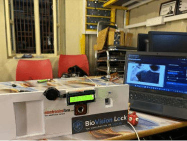
BioVision Lock is an intelligent security system that introduces a two-stage authentication mechanism by combining AI-based object detection with fingerprint recognition. The system uses the Arduino UNO Q to process visual input from a camera and identify a predefined authorised object, which acts as a unique “Visual Key.” Once the authorised object is detected, a servo motor automatically opens the fingerprint sensor cover, allowing the user to proceed with biometric authentication.
The fingerprint sensor verifies the user’s identity within a predefined time window, allowing a maximum of five attempts. Upon successful verification, a second servo motor unlocks the main door, while an LCD displays the access status and an LED and buzzer provide visual and audible feedback. The door remains unlocked for a configured duration of 10 seconds before automatically relocking. If fingerprint verification fails or the authentication time expires, access is denied, the fingerprint cover closes, and the system returns to its ready state.
By integrating artificial intelligence, computer vision, biometric security, and automated access control, BioVision Lock offers an innovative approach to smart security. Its distinctive feature is the use of an everyday authorised object as a visual authentication key, adding an additional layer of verification before fingerprint scanning. The project demonstrates the potential of combining AI and embedded systems to develop intelligent, user-friendly, and automated door-locking solutions.
Component List
| Name | Quantity |
| Arduino UNO Q | 1 |
| 16X2 LCD Display with IIC I2C Interface | 1 |
| R307 Optical Fingerprint Reader Sensor Module | 1 |
| Tower Pro SG90 RC Mini Servo Motor | 2 |
| LM2596 DC-DC Step-down Buck Module with Display | 1 |
| 12V 1AMP Power Adapter | 1 |
| Buzzer 5V | 1 |
| Zebronics Crystal Pro Webcam | 1 |
Step-by-Step Workflow
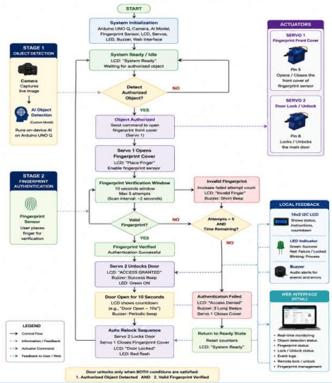
BioVision Lock – Flowchart Explanation
The flowchart shows how BioVision Lock performs two sequential authentication stages before opening the main door: AI object detection first, followed by fingerprint verification.
- Start & System Initialisation
The Arduino UNO Q initialises the camera, AI object-detection model, fingerprint sensor, LCD, two servo motors, LED, buzzer, and web interface. The system then enters the System Ready / Idle state. - AI Object Detection
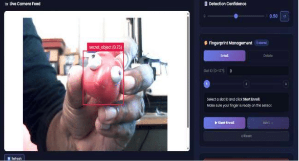
The camera captures the presented object and the on-device AI model checks whether an authorised object is present. If no authorised object is detected, the system continues waiting. The object-detection application runs on the UNO Q and triggers the authentication process when an object is detected. - Authorised Object Detected
When the required object is detected, the UNO Q commands Servo 1 to open the fingerprint front cover. Servo 1 is dedicated to the biometric cover and is not responsible for unlocking the main door. - Fingerprint Cover Opens
Servo 1 opens the cover and the LCD displays “Scanning Finger / Place finger.” The fingerprint authentication stage then begins. - Fingerprint Verification Window
The user places their finger on the sensor. The system allows a 10-second window with a maximum of five fingerprint attempts, with approximately 2 seconds between attempts. - Valid Fingerprint?
- YES: Authentication succeeds and the system proceeds to Servo 2.
- NO: The failed attempt is recorded. If attempts/time remain, the system continues fingerprint scanning.
- Servo 2 Unlocks the Main Door
Once the fingerprint matches a registered fingerprint, Servo 2 unlocks the actual door. Your code explicitly performs the door unlock after successful fingerprint matching. - Access Granted
The LCD displays “ACCESS GRANTED!”, the LED turns on, and the buzzer provides feedback. The door remains unlocked for the configured 10 seconds. - Automatic Relock
After 10 seconds, Servo 2 locks the main door, while Servo 1 closes the fingerprint cover. The system resets and returns to the Ready state for the next access attempt. - Authentication Failure
If all fingerprint attempts fail or the scan window expires, the system does not unlock Servo 2. The biometric cover is closed and the system returns to the ready state.
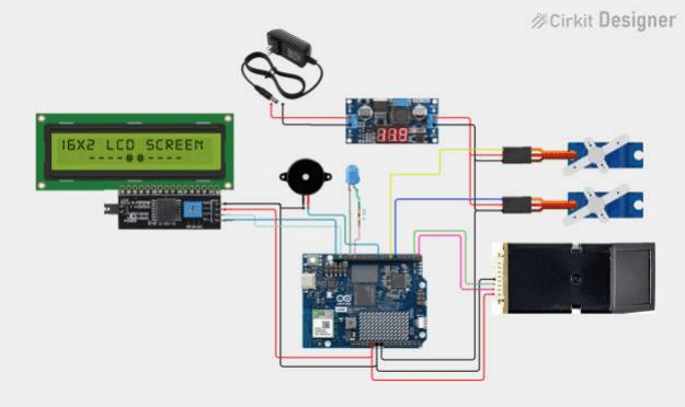
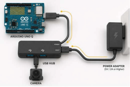
Block Diagram & Circuit Schematic
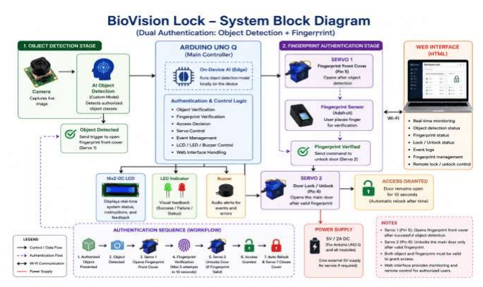
BioVision Lock block diagram represents a two-stage authentication system where Servo 1 and Servo 2 have completely different functions.
- Object Detection Stage
The camera continuously captures the presented object. The Arduino UNO Q runs the custom AI object-detection model locally and checks whether the detected object belongs to an authorised class.
Camera → AI Object Detection → Authorised Object Detected
When the correct object is detected, the UNO Q sends a command to Servo 1. Your code uses Servo 1 on Pin 5 for the biometric/front cover. - Servo 1 – Fingerprint Front Cover
Servo 1 does not unlock the door. Its purpose is to open the physical cover in front of the fingerprint sensor.
Authorized Object
↓
Servo 1
↓
Fingerprint Cover OPEN
↓
Fingerprint Sensor Accessible
Your code specifically opens the biometric servo when object detection starts and displays “Scanning Finger / Place finger” on the LCD. - Fingerprint Authentication
Once the cover is open, the user places their finger on the fingerprint sensor.
Your system provides a 10-second scanning window with up to 5 attempts. The Python application controls the scan timing and calls the Arduino fingerprint verification function.
The important security condition is: Authorized Object + Valid Fingerprint = Access Granted
If the fingerprint is invalid, the main door remains locked. - Servo 2 – Main Door Lock
After a valid fingerprint is identified, the Arduino UNO Q activates Servo 2, which is connected to Pin 6 and is responsible for the actual door lock.
The sequence is:
Valid Fingerprint
↓
Authentication Successful
↓
Servo 2
↓
Main Door UNLOCKED
Your code calls unlockDoor() after a successful fingerprint match, changing Servo 2 to the unlocked position. - Access Granted and Automatic Relock
After authentication, the door remains unlocked for the configured 10 seconds. The LCD shows the remaining lock time, while the buzzer provides periodic feedback.
After 10 seconds:
Servo 2 → Door LOCKED
Servo 1 → Fingerprint Cover CLOSED
System → Ready
This automatic closing and reset behaviour is implemented in the Arduino state machine. - LCD, LED and Buzzer
The 16×2 I2C LCD provides local information such as:
System Ready
Scanning Finger
Place finger
ACCESS GRANTED!
Invalid Finger
Door UNLOCKED
Lock in 5s
The LCD is directly integrated into the Arduino control code.
The LED provides visual status and the buzzer provides audible alerts. - HTML Web Interface
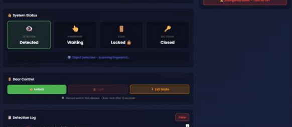
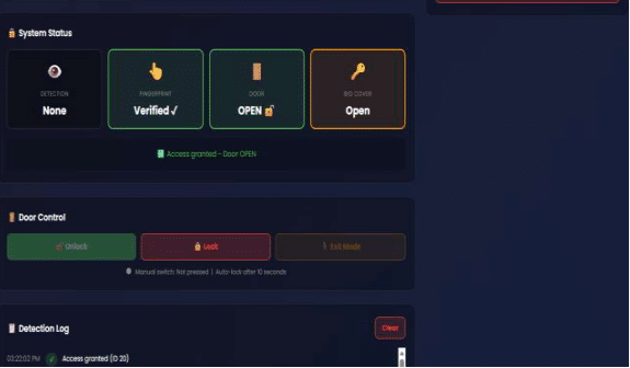
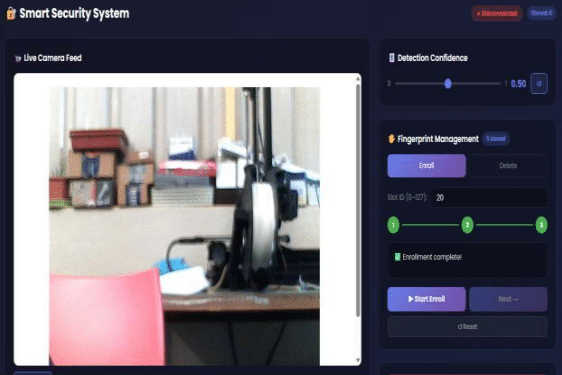
The Arduino UNO Q also runs the HTML web interface, which communicates with the
system and displays:
Object detection status
Fingerprint verification status
Door status
Biometric-cover status
Scan attempts
System state
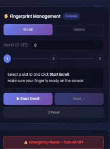
Fingerprint enrollment/deletion
Remote door control
The web application receives these system states from the Arduino through the Bridge interface.
Complete working sequence
Object Presented
↓
AI Detects Authorised Object
↓
Servo 1 Opens Fingerprint Front Cover
↓
Fingerprint Sensor Activated
↓
User Places Finger
↓
Fingerprint Verified?
↓ YES
Servo 2 Unlocks Main Door
↓
Access Granted
↓
10 Seconds
↓
Servo 2 Locks Door + Servo 1 Closes Cover
↓
System Ready
AI / ML Model Details
If your project does not use AI/ML, write “Not Applicable” — but note that Physical AI projects score higher on Innovation
| Model Used | YOLO-Pro |
| Training Platform | Edge Impulse |
| Accuracy | mAP@50 1.00 (100%), mAP@50–95 0.60 (60%) |
| Dataset | e.g. 29 images — 24 training, 5 testing |
Brief Description & Limitations
How does the model work in your project? When does it fail or degrade?
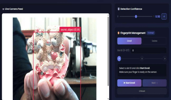
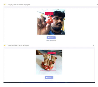
The YOLO-Pro model trained in Edge Impulse performs real-time detection of the authorised object using the Arduino UNO Q camera and on-device AI. When the authorised object is detected, it triggers Servo 1 to open the fingerprint cover, allowing the second authentication stage to begin.
The model may degrade when the object is partially hidden, viewed from an unfamiliar angle, too far from the camera, poorly illuminated, or affected by a cluttered background. Since the dataset contains a limited number of images and one object class, detection performance may reduce in conditions that differ significantly from the training images. The model achieved 1.00 mAP@50, while the stricter mAP@50–95 was 0.60, indicating that precise object localization can be more challenging than basic object detection.
Code Structure
The BioVision Lock software is divided into AI detection, authentication, actuator control, display, state management, and web-interface functions.
| Function | Purpose |
| setup() | Initializes the LCD, fingerprint sensor, Servo 1, Servo 2, LED, buzzer, door switch, and Arduino UNO Q Bridge. It places both servos in their secure starting positions. |
| loop() | Main execution function. Continuously processes Bridge communication, manual switch input, authentication states, timers, LCD updates, and automatic door locking. |
| on_detections() | Receives AI object-detection results. When an object is detected, it starts the fingerprint authentication process with a 10-second window and up to 5 attempts. |
| scanFingerprint() | Reads the fingerprint, converts the image, searches the stored fingerprint templates, and verifies the user. If valid, it triggers door unlocking. |
| openBioServo() | Opens Servo 1, which is the fingerprint sensor’s front cover |
| closeBioServo() | Closes Servo 1 after authentication failure, timeout, or completed access. |
| unlockDoor() | Activates Servo 2 to unlock the actual main door and updates the door status. |
| lockDoor() | Activates Servo 2 to return the main door to the locked position. |
| updateDisplay() | Displays the current system status on the 16×2 I2C LCD |
| set_led_state() | It turns on the LED, opens Servo 1, and starts the fingerprint scanning state. |
| set_door_state() | Provides remote/manual control of Servo 2 for locking or unlocking the door through the web interface. |
| verify_finger() | Bridge function that calls scanFingerprint() so the Python/AI application can request fingerprint verification. |
| resetAll() | Returns the complete system to a secure state: door locked, fingerprint cover closed, LED off, and state set to IDLE. |
| on_fp_enroll_start() / fp_enroll_step() | Handles registration of new fingerprints through the web interface. |
| on_fp_delete() | Deletes a stored fingerprint ID when requested through the web interface. |
| on_set_door_state() | Receives remote door-control commands from the HTML interface and updates the door state |
| on_reset_system() | Provides a web-based system reset and returns the authentication system to IDLE. |
Overall function flow
on_detections()
↓
set_led_state()
↓
openBioServo() — Servo 1 opens fingerprint cover
↓
scanFingerprint() / verify_finger()
↓
Valid fingerprint?
↓ YES
unlockDoor() — Servo 2 unlocks main door
↓
10-second access period
↓
lockDoor() — Servo 2 locks door
↓
closeBioServo() — Servo 1 closes fingerprint cover
↓
resetAll() / IDLE
This structure separates the AI decision, biometric verification, and physical door control, making the BioVision Lock system easier to manage and expand.
Testing and Result
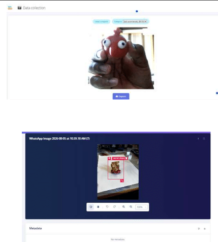
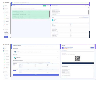
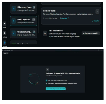
Steps: From Object Training in Edge Impulse to Arduino App Lab
- Collect Object Images
Capture multiple images of the authorised visual key/object from different angles, distances, backgrounds, and lighting conditions. In your project, the object is the red visual key. - Create an Edge Impulse Project
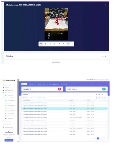
Create a new project in Edge Impulse and select Object Detection as the learning objective. - Upload and Label the Dataset
Upload the captured images to the Edge Impulse Data Acquisition/Dataset section. Draw bounding boxes around the authorised object and assign the class label, such as secret_object. - Split the Dataset
Divide the dataset into training and testing sets. Your current project uses approximately 81% training and 19% testing data. - Create the Impulse
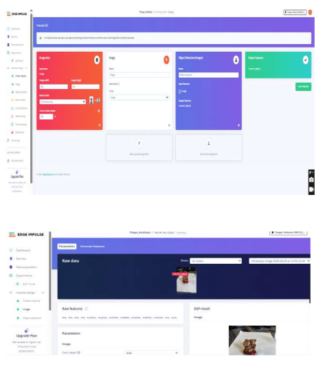
Configure the image processing pipeline and select the Object Detection learning block. This prepares the images for training. - Generate Features
Run Generate Features to convert the training images into the feature representation required by the object-detection model. - Train the YOLO-Pro Model
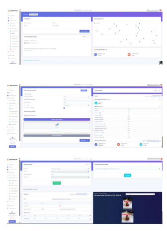
Train the object detector using YOLO-Pro in Edge Impulse. Your model was trained using the Edge Impulse platform with GPU processing. - Evaluate the Model
Use Model Testing to evaluate the trained model on unseen test images. Your model
achieved:
mAP@50: 1.00 / 100%
mAP@50–95: 0.60 / 60%
Class: secret_object - Optimise and Prepare the Model
Select the appropriate model format/optimization for deployment on the Arduino UNO Q. Edge Impulse provides deployment options and performance estimates for the target device. - Build the Deployment
Build the trained object-detection model/application for the target environment. The resulting model is prepared to perform on-device inference rather than depending on cloud processing. - Add Object Detection to Arduino App Lab
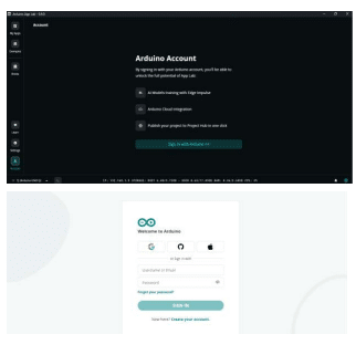
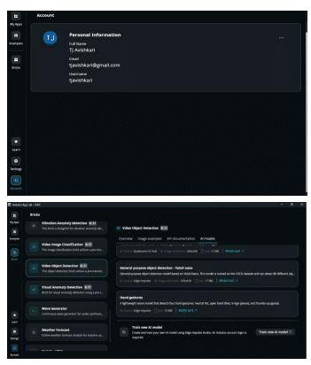
Open Arduino App Lab for the Arduino UNO Q and create/open your BioVision Lock application. Add the Video Object Detection brick/component and configure it to use the trained object-detection model.
Screenshot images of data collection and training
Next Step: Develop coding with required libraries
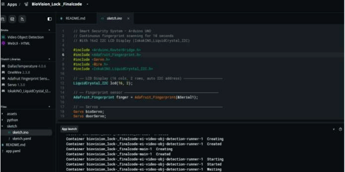
Arduino Libraries Required for BioVision Lock Based on your Arduino UNO Q code, the main Arduino libraries required are:
| Library | Purpose |
| Arduino_RouterBridge | Communication between the Arduino UNO Q microcontroller side and the Python/App Lab side |
| Adafruit Fingerprint Sensor Library | Fingerprint enrollment, image capture, template search, and verification |
| Servo | Controls the two servo motors — Servo 1 for the biometric cover and Servo 2 for the main door |
| Wire | Wire I2C communication with the 16×2 LCD |
| IskakINO_LiquidCrystal_I2C | Controls the 16×2 I2C LCD display |
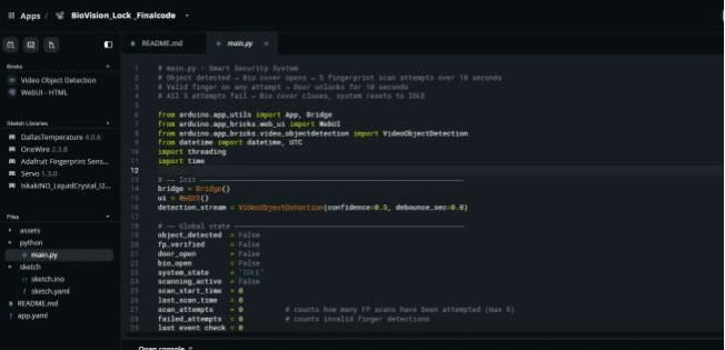
Python code for object detection and connecting to a web URL
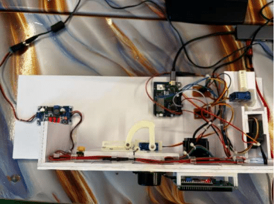
For making the project more presentable, 3D-printed components were incorporated using open-source designs from Thingiverse and adapted to fit the BioVision Lock hardware. The printed parts improve the overall appearance, component mounting, protection, and professional presentation of the prototype.
Project Photos and Samples