


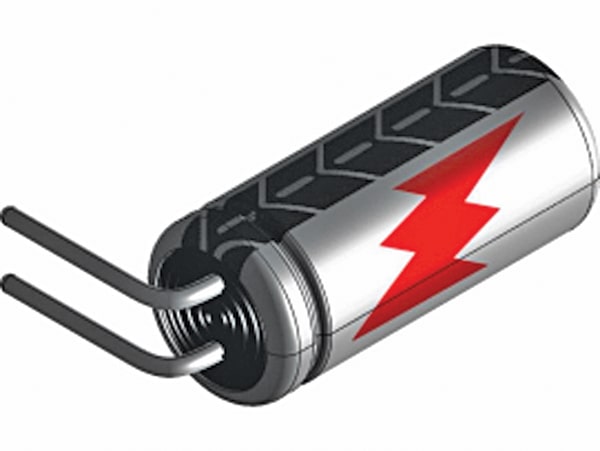
During repairs of vacuum tube equipment, switch-mode power supplies, microwave ovens, or similar systems, buffer or reservoir capacitors can retain potentially lethal voltages even after power is removed, requiring safe discharge. A high-voltage capacitor discharge system provides controlled energy dissipation. Fig. 1 shows a typical high-voltage capacitor that must be discharged before servicing.
POC Video Tutorial
Some practitioners recommend short-circuiting charged capacitors with an insulated screwdriver. This method should be avoided. The resulting high discharge current can damage the capacitor and present a serious safety risk. Capacitors may also spark or fail violently. Fig. 2 highlights this hazard, as capacitors can retain dangerous high voltage for extended periods.
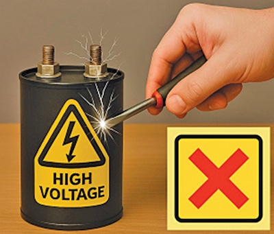
Fig. 3 illustrates a safer method for discharging a capacitor using a bleeder resistor. Passing the charge through a suitable power resistor limits current flow and reduces both component stress and operator risk.

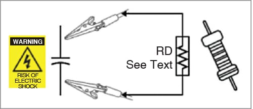
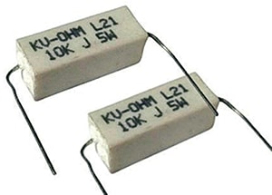
The simple arrangement shown in Fig. 3 is suitable for capacitor voltages up to 600V DC. A 4.7kΩ, 10W power resistor is generally adequate for this purpose. Initial tests used two 10kΩ (±5%), 5W ceramic-encased wire-wound resistors connected in parallel as the bleeder resistor (RD), and the setup performed reliably. Fig. 4 shows the resistors used for discharging.
One limitation of this basic method is the need to repeatedly check the capacitor voltage with a DC voltmeter to confirm that discharge has reached a safe level.
| Parts List |
| Semiconductors: D1-D4 – 1N4007 rectifier diode ZD1 (1N4734A) – 5.6V, 1W Zener diode LED1, LED2 – 5mm LED amber/yellow Resistors (all 1/4-watt, ±5% carbon), unless stated otherwise: R1, R2 – 22kΩ, 5W R3, R4 – 330Ω NTC – 3Ω Capacitors: – 150µF, 450V electrolytic (for charging) Miscellaneous: Red, black – Alligator clips (two) – Wires – Capacitor to be discharged |
A more practical approach is a dedicated capacitor discharge probe system that keeps the circuitry simple while providing reliable, visible operation. Fig. 6 shows the complete circuit with a bridge rectifier and LED indicators.

