
Humanoid robotics is gaining popularity, though a common misconception remains that it is complex and expensive. This system is designed to simplify entry into the field, featuring a life-size humanoid robotic arm with eight degrees of freedom: two at the shoulder, one at the elbow, and one for each finger.
The design emphasises simplicity in both mechanical and electronic aspects. Forming part of a larger humanoid robot named VulcanV1, the arm can be controlled using an Arduino with dedicated code to manage each joint and degree of freedom. Servo motors at every joint enable precise angular movement across all axes.
POC Video Tutorial
The system has applications in full-scale humanoid robots, cobots, and intelligent robotic arm designs. The entire setup is custom-designed by the author and can be readily 3D printed, assembled, and operated using the required components and software.

The Author’s prototype in Fig. 1 shows a life-size humanoid robotic arm with articulated joints and wiring layout.
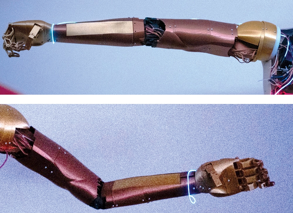
This arm consists of shoulder, elbow, wrist, and finger sections, each driven by servo motors that provide precise angular control. Electrical wiring runs internally through the arm segments, connecting all actuators to the central controller. When powered, the Arduino sends control signals to individual servos based on programmed instructions. Each joint moves independently, allowing coordinated motion similar to a human arm. The glowing highlights indicate active joint regions where rotation or movement occurs. The fingers are capable of gripping and releasing objects through synchronised servo action. Overall, the system converts programmed commands into mechanical motion for accurate positioning and manipulation. This makes it suitable for humanoid robots, assistive devices, and collaborative robotic applications.
This system requires 3D-printed structural parts along with electronic components for servo control. The system can be driven using either an Arduino Mega or an Arduino Uno paired with a dedicated servo driver module. Depending on the load and motion requirements of the arm, three types of servo motors are selected to ensure adequate torque and smooth operation.
For testing and operation, a 12V or 24V DC supply can be used to power the motors, either via an AC-DC adaptor or a suitable battery. The Arduino must be powered separately with a stable 5V regulated supply, such as through a USB connection or an external 5V source, to ensure reliable performance.
All required electronic components are listed in Table 1 for the Bill of Materials, while the mechanical parts, materials, and tools are listed in Table 2.
| Table 1: Electronic components | |||
| Item | Description | Quantity | Specifications/Notes |
| Arduino board | Microcontroller board | 1 | ≥8 PWM pins (Arduino Mega recommended if no driver is used) |
| PCA9685 servo driver (optional) | PWM expansion module | 1 | 16-channel |
| High-torque servo (25kg·cm) | Servo motor | 1 | 4.8V-6.8V, ~40mm×20mm×40.5mm |
| High-torque servo (DH03-X/ASME-MRB) | Heavy-duty servo motor | 2 | 180kg·cm–360kg·cm, ~95.5mm×60.5mm×102.6mm |
| Micro servo (SG90/MG90S) | Mini servo motor | 5 | ~22.8mm×12.2mm×28.5mm |
| 5V power supply | Regulated supply | 1 | 20A |
| 12V/24V power supply | Motor supply | 1 | 30A (24V recommended) |
| Servo extension cables | Male-female cables | 15 | 30cm |
| 14AWG wires (red and black) | Power wiring | 2m each | High-current connections |
| 3-prong power cable | AC input cable | 1 | Spare |
| Table 2: Mechanical parts, materials, and tools | |||
| Category | Item Description | Quantity | Specifications/Notes |
| Mechanical hardware | M3 screws (8mm) | 50 | Standard |
| M3 screws (12mm) | 15 | Standard | |
| M3 screws (18mm) | 10 | Standard | |
| M3 screws (20mm) | 14 | Standard | |
| M3 nuts | 20 | Standard | |
| M4 screws (8mm) | 4 | Standard | |
| M4 screws (20mm) | 10 | Standard | |
| M4 nuts | 10 | Standard | |
| M3 washers | 5 | Standard | |
| M4 washers | 3 | Standard | |
| General screws and nuts | — | Miscellaneous | |
| Actuation accessories | Servo arm (25T) | 1 | Usually included with servo |
| Wiring and electrical | Insulating tape | 1 roll | — |
| Zip ties | ~50 | 10cm | |
| 3D printing materials | PLA filament | 2kg | 1.75mm |
| Nylon filament (optional) | 200g | For high-stress parts | |
| Additional mechanical parts | Fishing nylon thread | 1 roll | 0.4mm (finger actuation) |
| Aluminium servo bracket | 1 | ~58mm×37mm×25.5mm | |
| Tools required | Wire stripper | 1 | Self-adjusting |
| Standard pliers | 1 | — | |
| Cutting pliers | 1 | — | |
| Screwdriver set (Phillips) | 1 set | — | |
| Hex screwdriver | 1 | — | |
| Soldering iron | 1 | — | |
| Solder wire | 1 roll | Tin | |
| Multimeter | 1 | — | |
| Drill machine | 1 | — | |
| Drill bit set | 1 | 2.78mm commonly used | |
| Bench vise | 1 | — | |
| 3D printer | 1 | Minimum 15cm×15cm×25cm build volume | |
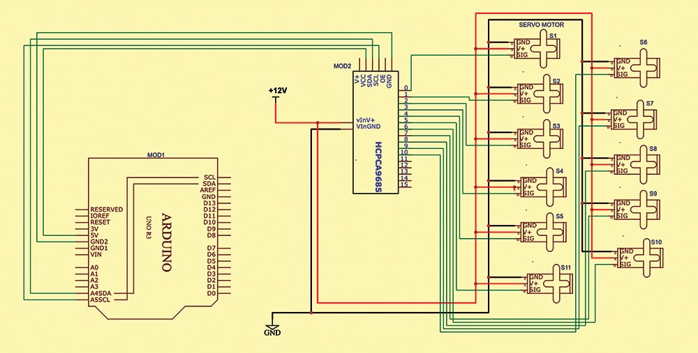
Humanoid Robotic Arm Circuit diagram
Fig. 2 shows the circuit diagram of the full-scale humanoid robotic arm. The system is built around an Arduino Uno (MOD1) and a PCA9685 servo driver module (MOD2), along with multiple servo motors, including high-torque (25kg·cm), heavy-duty (DH03-X/ASME-MRB), and micro servos (SG90/MG90S), supported by essential electrical components.