




Project Demo Video:
Component List
| ID | Name | Designator | Quantity |
| 1 | M5Stack CoreS3-SE (ESP32-S3, 2″ 320×240 touch, speaker, mic, Wi-Fi, RTC) | MOD1 | 1 |
| 2 | ADS1115 16-bit 4-channel I²C ADC | U1 | 1 |
| 3 | ACS723 low-current Hall current sensor (±5 A, isolated) | U2 | 1 |
| 4 | Resistor 4.7 kΩ 1% (pack-divider top leg) | R1 | 1 |
| 5 | Resistor 1 kΩ 1% (pack-divider bottom leg) | R2 | 1 |
| 6 | Resistor 10 kΩ 1% (NTC divider fixed leg) | R7 | 1 |
| 7 | Capacitor 100 nF 50 V (ADC anti-alias) | C1 | 1 |
| 8 | NTC thermistor 10 kΩ B3950 (pack temperature) | RT1 | 1 |
| 9 | NEO-6M GPS module (UART) | GPS1 | 1 |
| 10 | 2 A slow-blow fuse + holder (load-path protection) | F1 | 1 |
| 11 | 3S Li-ion bench pack, 12.6 V max, protected | BAT1 | 1 |
| 12 | 12 V 21 W incandescent lamp (calibration/demo load) | LOAD1 | 1 |
| 13 | USB power bank (independent power for the CoreS3-SE) | PWR1 | 1 |
| 14 | Grove/JST cabling, perfboard, wire, enclosure | — | — |
The purchasable bill of materials — with manufacturer and DigiKey part numbers, quantities, live prices, purpose, and schematic references — is in the public DigiKey MyList: Digikey link (as-built).
The sensors run directly from the CoreS3-SE’s own regulated 3.3 V header rail, so no LDO regulator is needed — a deliberately simpler, honest design.
Project Explanation Step By Step:
Budget EV riders in India get almost no trustworthy information from their vehicle: a coarse fuel-gauge-style bar, no temperature insight, no honest range, and no idea whether the next charger is actually reachable. The Smart EV Battery Companion is a small, independently powered touchscreen device that reads real electrical signals from a battery on a safe low-voltage bench rig, runs a validated state-of-charge estimator on-device, and — over Wi-Fi — finds nearby charging stations, routes to them, and ranks them by whether they are reachable on the energy you have left.
Crucially, every value on screen is labelled by where it came from (live sensor, laboratory-dataset replay, or estimate), so the device never overstates what it knows. The IoT element (live charger discovery + routing + offline cache) is central to the rider’s decision, not a bolt-on.
What makes it different from “just another battery dashboard”
- Confidence-aware SoC, not a fake number — the OCV-corrected extended Kalman filter reports a LEARNING → READY → DERATED state with confidence, and openly derates when cold.
- Reachability, not just a charger list — stations are ranked reachable / marginal / out-of-range using a conservative range plus a reserve margin.
- Honesty as a design rule — live, replayed, and estimated values are visibly distinguished by a source badge (LIVE BENCH vs SIMULATED); no cell-balance claims, no invented replacement date, no “works on every EV” claim.
- Validated with published lab data — the estimator was validated against the CALCE INR18650-20R dataset with a held-out split; error is reported with its temperature limitation stated openly.
The five screens
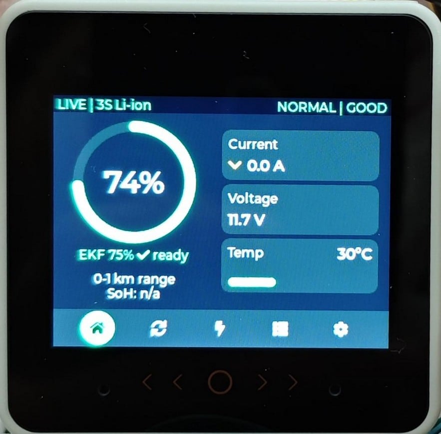
- Dashboard: SoC arc with estimator state + confidence, conservative and nominal range, live pack voltage / current / temperature, charge/discharge indicator, and a persistent source badge.
- Health: data-quality gauge, live pack-voltage trend, per-cell average voltage, and an honest “SoH: needs a full cycle to measure” status (no fabricated health percentage).
- Charging (IoT): nearby chargers from Open Charge Map ranked by reachability, turn-by-turn route distance/time with an on-device route map, GPS status, and ONLINE/CACHED/OFFLINE data-source labelling.
- Session / Energy: live energy discharged/charged (Wh), peak power, a real-time power (W) trend, and session time— all integrated from measured pack V × I.
- Settings: theme (dark / light / auto-by-time), brightness, power-saver, Wi-Fi, data logging, current zero-calibration, and a clearly separated demo simulation mode.
Hardware Design and Sensing
The device measures three real quantities from the bench pack:
- Voltage: a resistor divider (4.7 kΩ / 1 kΩ) scales the pack voltage into the ADS1115’s input range on channel A0. Calibrated in firmware against a multimeter (meter 11.32 V ≈ display 11.3 V); the divider-ratio constant (5.553) absorbs resistor tolerance, so precision parts are unnecessary.
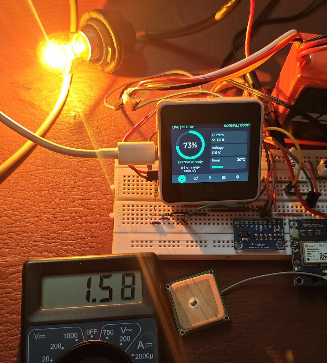
- Current: an isolated ACS723 Hall sensor in the pack’s high side, on channel A3. Zero-offset is nulled at startup with the load off; sensitivity was calibrated against a series multimeter with a 21 W lamp (meter 1.61 A). Positive = charging, negative = discharging.
- Temperature: a 10 kΩ B3950 NTC on a divider into the ESP32-S3 ADC, converted with the beta equation; the firmware refuses to read an unconnected sensor so a missing NTC honestly shows “–“.
Why the sensors run at 3.3 V: the ADS1115 and ACS723 are powered from the CoreS3-SE’s regulated 3.3 V header pin so their I²C levels match the ESP32-S3 natively — no level shifter and no LDO needed. Sensor I²C runs on a dedicated FreeRTOS task (core 0) so the touchscreen (core 1) never stalls.
Battery Intelligence: Algorithms and Validation
The SoC estimator was validated before any on-hardware work, in Python, against the CALCE INR18650-20R (NMC) dataset. Parameters were tuned on 25 °C DST only; all other runs (including 0 °C and 45 °C) are held out.
| Estimator | Held-outMAE(pp) | Worst(pp) |
| Voltage-only OCV lookup | 12.75 | 73.88 |
| Coulomb counting (ideal init) | 0.70 | 2.15 |
| Coulomb counting (+10 pp init error) | 10.69 | 12.15 |
| OCV-corrected EKF (1st-order RC) | 2.08 | 15.49 |
EKF by temperature: 0.38 pp @ 25 °C, 0.96 pp @ 45 °C, 8.27 pp @ 0 °C.
The device runs the same algorithm on-device, configured for the live 3S bench pack. SoC uses coulomb counting under load (immune to voltage sag) anchored to rest-gated, IR-compensated OCV correction — the approach a production fuel gauge uses, so the reading does not bounce when a load is removed.
Stated limitation: SoC accuracy is temperature-dependent (±3% at 25 °C, worse when cold), which is why the UI exposes a confidence / DERATED state rather than a single number pretending to be exact.
IoT: Charging Discovery, Routing, and Offline Resilience
The IoT layer runs on a separate FreeRTOS task (no HTTP/TLS on the UI thread):
- Live charger discovery from Open Charge Map over verified TLS.
- Turn-by-turn routing from openrouteservice (distance, duration, steps, and a decoded route polyline drawn on-device); rows label Air vs Road.
- Reachability ranking from the conservative range + reserve margin.
- Offline cache in NVS with ONLINE/CACHED/OFFLINE labels and data age (a Wi-Fi-loss test confirmed labelled fallback to cached data).
- GPS via NEO-6M with truthful GPS FIX / LAST FIX / CONFIGURED states, and it also sets the RTC clock from GPS UTC.
Coding Explanation and Configuration
The firmware is built with PlatformIO + Arduino + M5Unified + LVGL 9.5 for the M5Stack CoreS3-SE — not the Arduino IDE — because PlatformIO pins exact library versions for reproducibility.
Build and flash:
cd cores3_firmware
pio run # build
pio run –target upload –upload-port /dev/ttyACM0 # flash
Key libraries (pinned in platformio.ini): M5GFX 0.2.28, M5Unified 0.2.21, lvgl 9.5.0, ArduinoJson 7.4.3, TinyGPSPlus 1.1.0.
Module map:
| Path | Purpose |
| src/platform/ev_sensors.cpp | ADS1115 + ACS723 + NTC sampling on a background task |
| src/model/ev_live_source.c | Sensor reading → battery state; SoC (coulomb + rest-gated OCV) |
| src/model/ev_estimator.c | On-device OCV-corrected EKF (pack-configurable) |
| src/ui/ | Five LVGL screens, nav, alert banner, runtime theme |
| src/service/ | Open Charge Map + openrouteservice clients (verified TLS) |
| src/platform/ev_time.*, ev_power.* | RTC (GPS-synced) and AXP2101 power management |
| analysis/ | Python estimator validation (reproducible) |
The whole system is built around one shared application-state pipeline with three interchangeable sources — live bench, dataset replay, and deterministic fault test — so the UI, alerts, logger, and IoT services all read one coherent model.
Blocking work (I²C, Wi-Fi/TLS) is isolated on core 0; the LVGL UI on core 1 only reads snapshots, which keeps the touchscreen responsive. Last build footprint: RAM 49.6%, flash 24.1%.
Coderepository: click here
Connection Explanation
The bench rig is wired for safety and measurement accuracy:
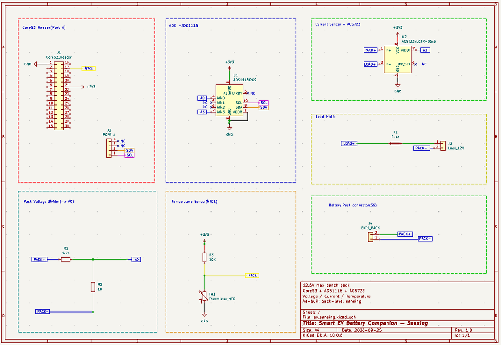
- Voltage sense: pack + → R1 (4.7 kΩ) → node → R2 (1 kΩ) → pack −; the node goes to ADS1115 A0 with a 100 nF anti-alias cap. Powered from the pack’s balance/main leads at low voltage only.
- Current sense (load path): PACK+ → ACS723 IP+ → IP− → 2 A fuse → 12 V lamp → PACK−. The ACS723 is galvanically isolated and sits in the high side; its VOUT goes to ADS1115 A3. Thick wire is soldered directly to IP+/IP− so the ~1.6 A load current never passes through the breadboard.
- Temperature: 3.3 V → 10 kΩ → node (→ CoreS3 GPIO8) → NTC → GND.
- Power/I²C: ADS1115 and ACS723 run from the CoreS3-SE 3.3 V header pin; I²C SDA/SCL on Grove Port A (G2/G1). PACK− is tied to the common ground — essential for a stable voltage reading.
- The CoreS3-SE is powered independently by a USB power bank, never by the pack under test. KiCad schematic: hardware/ev_sensing/.
Testing
| Quantity | Result |
| Voltage | Multimeter 11.32 V vs display 11.3 V — matches after firmware calibration; stable once PACK− grounded |
| Current | 0.0 A; 1.6 A under the 21 W lamp, matching a series multimeter (1.61 A) |
| Temperature | ~27 °C ambient; rises with a warm hand, falls on a cold object; rejects an unconnected sensor |
| SoC under load | Drops correctly while discharging; no bounce-back when the load is removed (rest-gated OCV) |
| Estimator | Held-out CALCE validation (table above), 12 per-run plots |
| IoT | Live Bengaluru charger fetch + routing; Wi-Fi-loss test shows labelled CACHED fallback |
| Stability | Splash-freeze and touch-break root-caused and fixed; runs without reset |
Real-World Application and Production Path
- A retrofit companion for budget EVs — independently powered, non-invasive.
- Compatibility is presented as a bounded matrix, not “any EV”.
- A production version would add automotive-grade isolation, surge/load-dump protection, rated connectors/fusing, a wide-input automotive DC/DC, and a shunt-based current front-end (INA226) for finer resolution. A gated OTA path (versioned battery profiles; optional signed dual-slot firmware) reuses the developer’s professional ECU/BMS OTA experience.
Limitations (stated plainly)
- SoC accuracy is temperature-dependent (±3% at 25 °C; ~8 pp at 0 °C) — shown as a confidence / DERATED state.
- The ±5 A current sensor is coarse below ~0.3 A; a demo uses a ~1.6 A load, and a shunt sensor is documented as the production upgrade.
- No cell-balance claim — the bench pack has protection, not active balancing.
- No verified replacement-date prediction from short observation.
- Estimator evidence is from a published single-cell NMC dataset, not a measurement of a full EV pack.
Schematics
Code
Firmware: cores3_firmware/ (PlatformIO).
Estimator validation: analysis/.
Hardware design + schematic : hardware/.
Laboratory data courtesy of the Center for Advanced Life Cycle Engineering (CALCE), University of Maryland. Citation: Zheng, Xing, Jiang, Sun, Kim, Pecht, “Influence of different open circuit voltage tests on state of charge online estimation for lithium-ion batteries,” Applied Energy 183, pp. 513–525, 2016.
