




The Smart Industrial Machine Safety Control System is an embedded safety solution built around the MAX32630FTHR development board. The system continuously monitors hazardous areas using proximity and motion sensors. When a worker approaches a machine beyond the configured safety distance, the controller evaluates the sensor data in real time and activates multiple safety measures.
These measures include audible and visual warnings, emergency machine shutdown through a safety relay, and wireless notifications to operators or supervisors. The system can also log safety events for maintenance and compliance purposes. Its modular architecture allows additional sensors and communication modules to be integrated, making it suitable for manufacturing plants, warehouses, CNC machines, conveyor systems, and robotic workstations.
“The Smart Industrial Machine Safety Control System is an embedded safety solution built around the MAX32630FTHR development board. The system continuously monitors hazardous areas using proximity and motion sensors. When a worker approaches a machine beyond the configured safety distance, the controller evaluates the sensor data in real time and activates multiple safety measures.
These measures include audible and visual warnings, emergency machine shutdown through a safety relay, and wireless notifications to operators or supervisors. The system can also log safety events for maintenance and compliance purposes. Its modular architecture allows additional sensors and communication modules to be integrated, making it suitable for manufacturing plants, warehouses, CNC machines, conveyor systems, and robotic workstations.”
Team Members
| S. No. | Name | Role / Contribution | Contact (Optional) |
|---|---|---|---|
| 1. | Cheepati Swathi | Hardware and Software Designer | [email protected] |
| 2. | G. Karthick Kumar Reddy | Software App developer | [email protected] |
| 3. | C. RajaSekhar Reddy | Circuit Designer | [email protected] |
Component list
The following components are suitable for building and demonstrating the supplied program.
| No. | Component | Quantity | Purpose |
|---|---|---|---|
| 1 | MAX32630FTHR development board | 1 | Runs the C++ program |
| 2 | PIR motion sensor, such as HC-SR501 | 1 | Detects human movement |
| 3 | Red LED | 1 | Indicates the alert state |
| 4 | Green LED | 1 | Indicates the normal state |
| 5 | Current-limiting resistors, typically 220–330 Ω | 2 | Limit LED current |
| 6 | Breadboard | 1 | Prototyping connections |
| 7 | Jumper wires | As needed | Connect components |
| 8 | USB cable | 1 | Programming and serial communication |
| 9 | Computer with Mbed-Studio IDE | 1 | Compiling, uploading, and monitoring |
Project overview
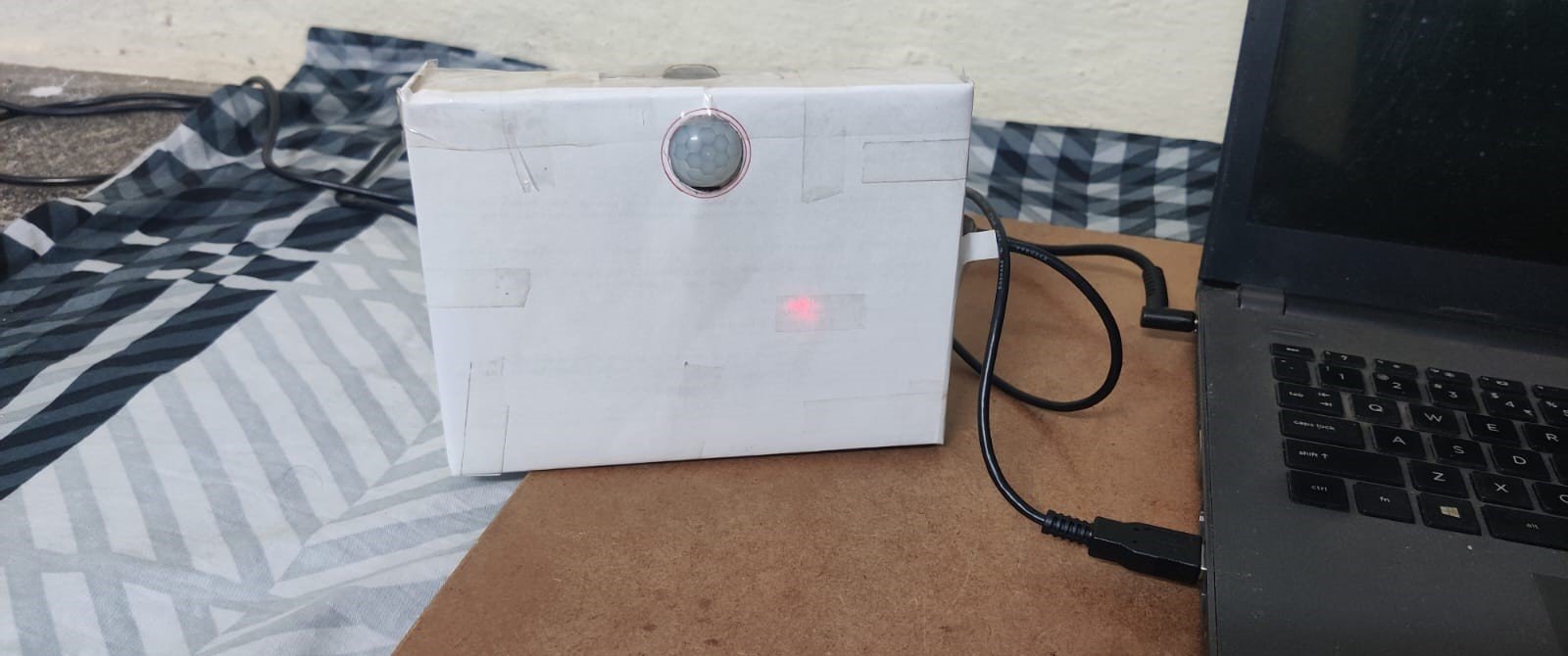
The project is designed to detect human movement using a PIR (Passive Infrared) motion sensor and indicate the system status using red and green LEDs. When motion is detected, the red LED turns ON and remains active for 20 seconds after the most recent motion signal. If motion continues, the timer restarts. When no motion is detected for 20 seconds, the red LED turns OFF and the green LED turns ON.
The system also sends status messages and a countdown through a serial terminal, allowing the user to monitor the operation in real time.
PIR motion sensor:
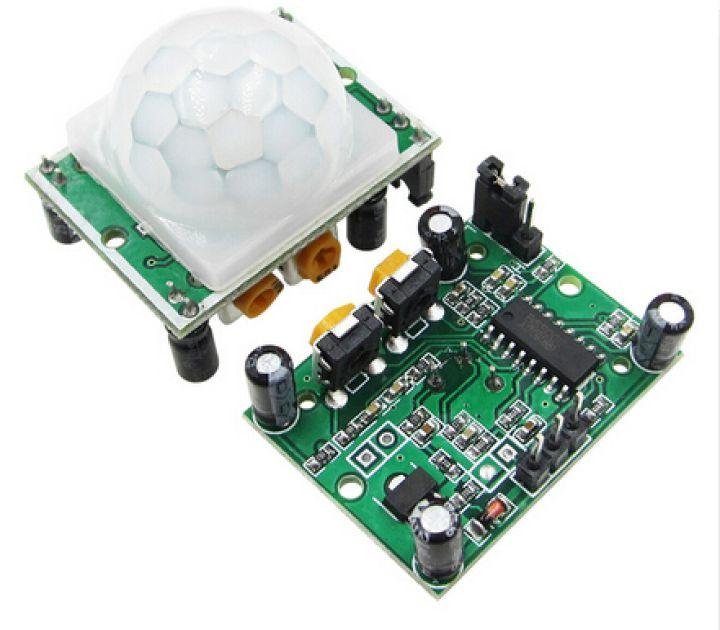
Detects changes in infrared radiation associated with moving people and provides a digital HIGH signal when motion is detected.
Mbed-compatible controller:
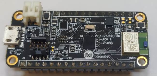
Reads the sensor signal, manages the 20-second timer, controls the LEDs, and sends serial messages.
Red and green indicators:
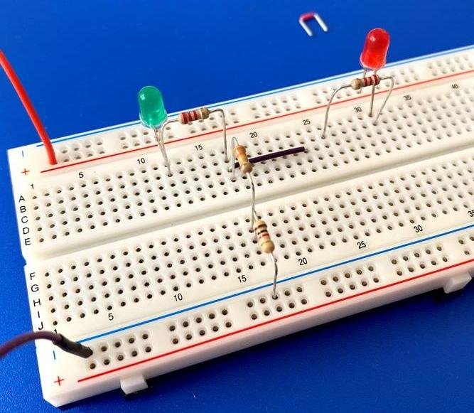
Red indicates motion detected or the alert state. Green indicates the normal waiting state.
Project objectives
- Detect human movement within the sensor’s coverage area.
- Provide visual warnings using red and green LEDs.
- Maintain the alert state for 20 seconds after the last detected motion.
- Display the remaining time through a serial terminal.
- Automatically return to the normal state when the timer expires.
Important safety limitation: The supplied code is a motion-detection demonstration, not a certified industrial machine safety controller. It does not switch off machinery or guarantee that a hazardous zone is clear. PIR sensors can miss stationary people and are not substitutes for appropriate safety-rated presence sensors, interlocks, and machine safety control circuits.
The code uses these exact pin assignments:
- PIR sensor output: P5_4
- Red LED output: P2_4
- Green LED output: P2_5
- Serial communication: USBTX and USBRX at 115200 baud
Check the pinout and electrical specifications of your particular development board before making the connections.
Project explanation step by step
Step 1: Power ON the system
Connect the development board to the computer using USB. The controller starts executing the program, initializes the sensor input, configures the LED outputs, and prepares serial communication.
Step 2: Initialise the safe indication
The function showGreen() turns the green LED ON and the red LED OFF. The terminal displays that the system is waiting for motion.
Step 3: Detect human movement
The controller continuously reads the digital output of the PIR sensor connected to P5_4. When the signal becomes HIGH, the controller treats it as a motion-detection event.
Step 4: Activate the alert indication
The showRed() function turns the red LED ON and the green LED OFF. A message appears on the serial terminal indicating that motion has been detected.
Step 5: Start and update the countdown
The controller measures elapsed time from the most recent HIGH signal. It displays the remaining time from approximately 20 seconds down to zero. Each new HIGH reading resets the timer.
Step 6: Return to the waiting state
If the PIR output remains LOW continuously for 20 seconds, the controller switches the red LED OFF, switches the green LED ON, and prints a completion message.
System flowchart
Start the system
Initialize PIR input, LEDs and serial terminal
Read PIR sensor
HIGH
Red ON, green OFF
Reset timer and display countdown
LOW
Check elapsed time
After 20 seconds: green ON
Repeat continuously with a 50 ms delay between loop iterations.
Coding explanation
The program is written in C++ using the Mbed API. Each section performs a specific function in the motion detection and indication process.
Header files
cpp
#include "mbed.h"
#include <cstdio>
#include <cstring>- mbed.h provides digital input/output, serial communication, timing, and thread-sleep functions.
- cstdio provides snprintf() for formatting the countdown message.
- cstring provides strlen() to determine the length of a text message.
Pin configuration
cpp
DigitalIn pir(P5_4);
DigitalOut redLED(P2_4);
DigitalOut greenLED(P2_5);
BufferedSerial pc(USBTX, USBRX, 115200);- pir reads the sensor’s digital output.
- redLED controls the red indicator.
- greenLED controls the green indicator.
- pc sends information to the computer through serial communication at 115200 baud.
The pin identifiers must match the actual development board and its Mbed target configuration.
Motion hold duration
cpp
constexpr auto MOTION_HOLD_TIME = 20s;This defines the duration for which the alert state remains active after the most recent HIGH sensor reading. The 20s literal is enabled by using namespace std::chrono;.
LED control functions
cpp
void showRed()
{
    redLED = 0;
    greenLED = 1;
}
void showGreen()
{
    redLED = 1;
    greenLED = 0;
}
The LEDs are configured as active LOW:
| State | Red output | Green output | Meaning |
|---|---|---|---|
| Normal | 1 | 0 | Waiting for motion |
| Alert | 0 | 1 | Motion detected / alert active |
This logic assumes the physical LED wiring is active LOW. The LEDs and their current-limiting resistors must be wired accordingly.
Serial message function
cpp
void printMessage(const char *message)
{
    pc.write(message, strlen(message));
}
This function sends a text message through the serial connection. strlen() calculates how many bytes should be transmitted.
Initial setup
cpp
pc.set_format(8, BufferedSerial::None, 1);
showGreen();
bool redActive = false;
int previousRemaining = -1;
auto lastMotionTime = Kernel::Clock::now();
The serial connection is configured for 8 data bits, no parity, and 1 stop bit (8-N-1). The system starts in the green state.
- redActive tracks whether the alert state is active.
- previousRemaining records the previously displayed countdown value.
- lastMotionTime stores the time reference used to calculate elapsed time.
Detecting motion
cpp
if (pir.read() == 1)
{
    lastMotionTime = now;
    if (!redActive)
    {
        redActive = true;
        showRed();
        previousRemaining = -1;
        printMessage("\r\nMotion detected! RED LED ON\r\n");
    }
}
Whenever the sensor output is HIGH, the timestamp is updated. If the red alert was not already active, the program activates the alert and prints the detection message.
Because the timestamp is refreshed on every HIGH reading, continued sensor output extends the alert period.
Calculating the remaining time
cpp
auto elapsed = now - lastMotionTime;
int remaining = 20 -
    duration_cast<seconds>(elapsed).count();
if (remaining < 0)
    remaining = 0;
The controller subtracts the elapsed whole seconds from 20. The remaining value is limited to zero so that negative countdown values are not displayed.
Updating the serial display
cpp
if (remaining != previousRemaining)
{
    char message[80];
    int len = snprintf(
        message, sizeof(message),
        "Red LED ON | Time remaining: %02d seconds\r\n",
        remaining);
    pc.write(message, len);
    previousRemaining = remaining;
}
The countdown message is transmitted only when the displayed second changes. %02d formats the number using at least two digits, such as 09, 08, and 07.
Ending the alert state
cpp
if (elapsed >= MOTION_HOLD_TIME)
{
    redActive = false;
    showGreen();
    printMessage(
        "Countdown complete. GREEN LED ON\r\n"
        "Waiting for motion...\r\n");
    previousRemaining = -1;
}
When 20 seconds have elapsed since the last HIGH reading, the program deactivates the alert, returns to the green indication, and resets the countdown display state.
Loop delay
cpp
ThisThread::sleep_for(50ms);This pauses the thread for approximately 50 milliseconds between loop iterations, reducing unnecessary continuous polling while keeping the input responsive for a demonstration.
Software configuration
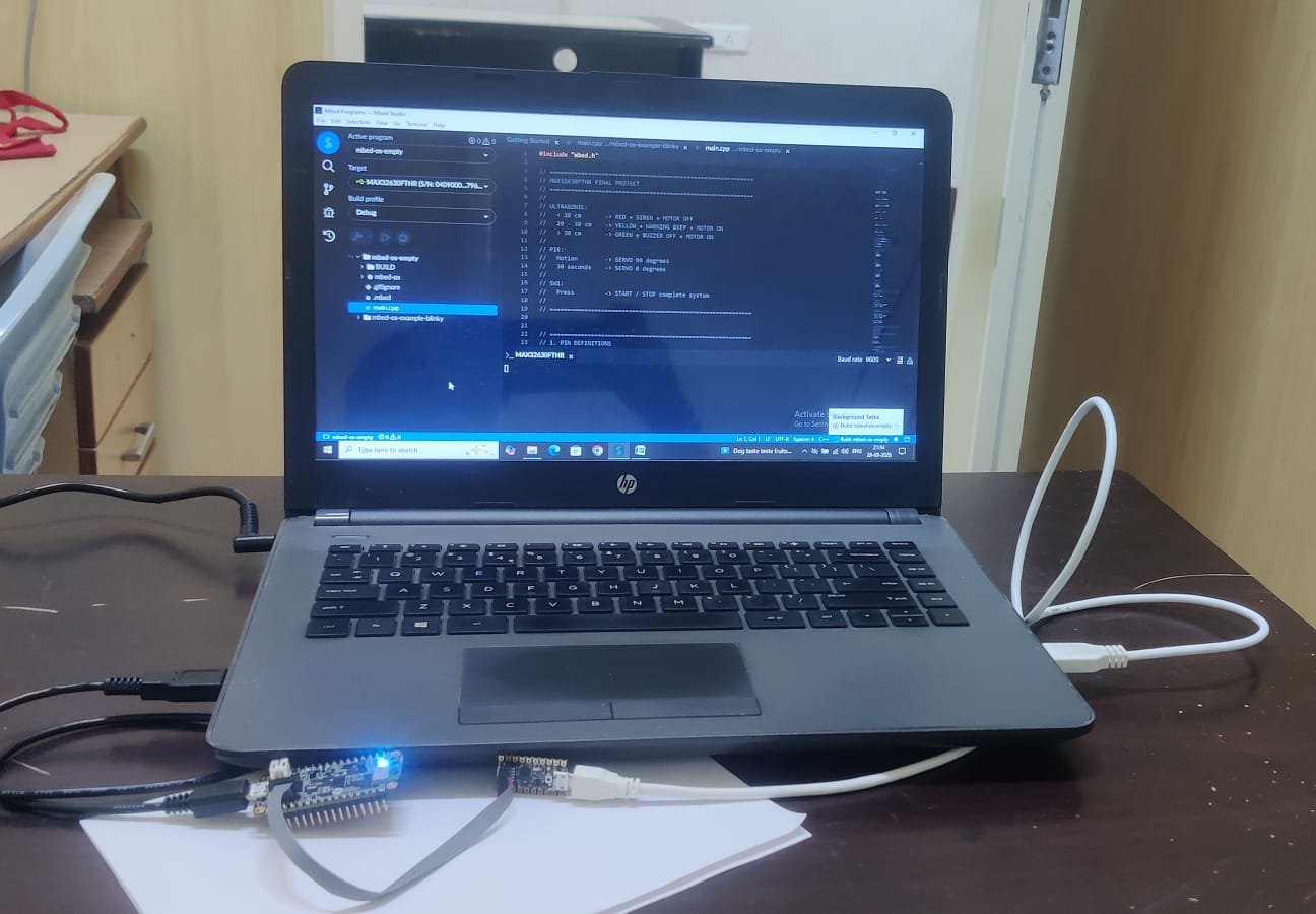
Required development environment
| Setting | Configuration |
|---|---|
| Programming language | C++ |
| Embedded framework | Arm Mbed OS / compatible Mbed environment |
| Source file | main.cpp |
| Sensor input pin | P5_4 |
| Red LED pin | P2_4 |
| Green LED pin | P2_5 |
| Serial baud rate | 115200 |
| Serial format | 8 data bits, no parity, 1 stop bit |
| Alert hold time | 20 seconds |
| Loop delay | 50 milliseconds |
The exact board model and Mbed OS version should be confirmed before compiling. The use of P5_4, BufferedSerial, and Kernel::Clock depends on the target and framework version. The Mbed LPC1768 platform documentation provides board-specific pinout and development information.

Mbed
+1
Configuration procedure
1. Create or open an Mbed-compatible C++ project.
2. Select the target board that matches your hardware.
3. Place the supplied code in main.cpp.
4. Ensure the project includes a compatible Mbed library and C++ standard-library support for chrono literals.
5. Compile the project and resolve any target-specific pin or API errors.
6. Connect the board to the computer and upload the compiled program.
7. Open the appropriate serial terminal and select 115200 baud, 8-N-1.
8. Power the PIR sensor and test the LEDs by moving within the sensor’s detection range.
Expected initial terminal output:
text
PIR Motion Detection Started
Status: GREEN - Waiting for motion
Connection explanation
PIR sensor connections
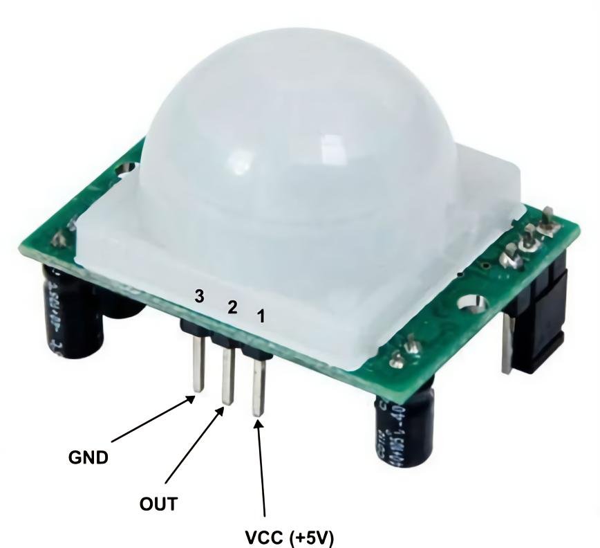
A typical HC-SR501 PIR sensor has three connections: VCC, OUT, and GND.
| PIR sensor pin | Development board connection | Purpose |
|---|---|---|
| VCC | Compatible supply voltage | Powers the sensor |
| OUT | P5_4 | Sends the motion signal |
| GND | GND | Common electrical reference |
The HC-SR501 commonly operates from a supply around 5 V, but its signal voltage and the development board’s input limits must be checked. Never connect a sensor output that exceeds the controller’s permitted input voltage.
LED connections
Because the code uses active-LOW LED control, a typical suitable arrangement is for each GPIO pin to sink current from an LED connected through a resistor to an appropriate positive supply rail.
| LED circuit | Controller connection | Operation |
|---|---|---|
| Red LED cathode | P2_4 | Output LOW turns it ON |
| Green LED cathode | P2_5 | Output LOW turns it ON |
| LED anodes | Through separate resistors to a compatible positive supply | Limits current |
| Supply return | Controller GND | Common reference |
Use a current-limiting resistor for each LED. The exact resistor value and supply voltage should be chosen according to the LED forward voltage and the board’s electrical specifications.
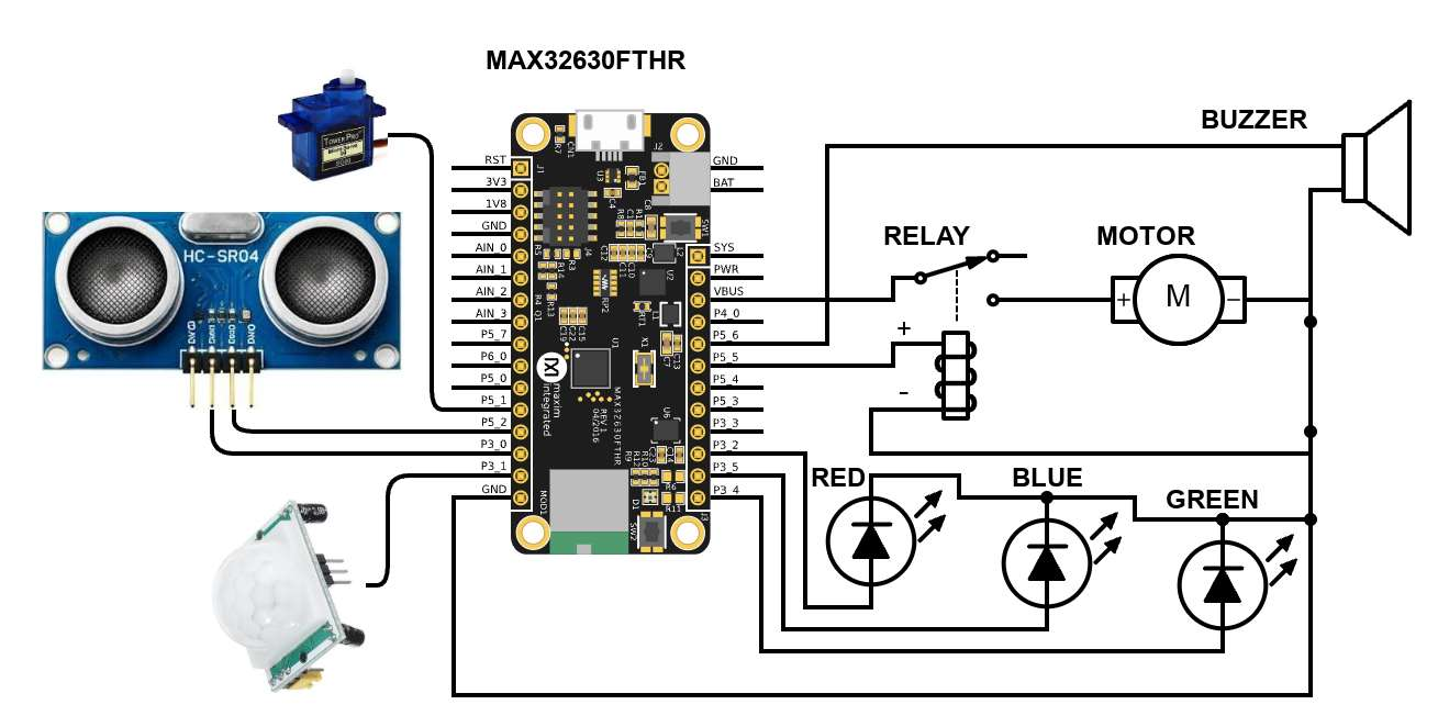
Circuit schematic
The following is a conceptual wiring schematic for the demonstration circuit. It is not a verified board-specific pinout drawing.
PIR motion sensor
VCC · OUT · GND
Mbed-compatible controller
P5_4: digital input
P2_4: red LED control
P2_5: green LED control
USB serial: 115200 baud
Red LED circuit
Resistor + LED
P2_4 sinks current
Green LED circuit
Resistor + LED
P2_5 sinks current
Computer / serial terminal
Receives startup messages, motion alerts and countdown updates over USB serial.
Planned but used only PIR
Simplified electrical representation
PIR SENSOR
==========
VCC  ---------------- Compatible supply
OUT  ---------------- P5_4
GND  ---------------- Controller GND

RED LED (ACTIVE LOW)
====================
Compatible +V -- Resistor -- LED Anode
                              LED Cathode -- P2_4

GREEN LED (ACTIVE LOW)
======================
Compatible +V -- Resistor -- LED Anode
                              LED Cathode -- P2_5

SERIAL COMMUNICATION
====================
USB connector -------- Computer
                       Serial terminal: 115200 baud
The board, supply rails, and sensor must share a suitable ground reference. Do not assume that every Mbed-compatible board uses the same physical pin locations or voltage limits. For the LPC1768, consult the manufacturer’s pinout and board documentation before wiring.
Mbed
+1
Testing and verification
Test the system first on a low-voltage bench setup, without connecting it to operating industrial machinery.
| Test | Procedure | Expected result |
|---|---|---|
| 1. Power-on test | Connect the USB cable and start the program | Green LED ON; startup message displayed |
| 2. Motion detection | Move in front of the PIR sensor | Red LED ON; green LED OFF |
| 3. Serial alert | Trigger the sensor | Motion detection message appears |
| 4. Countdown | Stop moving and wait for the sensor output to go LOW | Remaining-time messages decrease |
| 5. Continuous motion | Continue moving while the PIR output is HIGH | Timer is repeatedly refreshed |
| 6. Return to normal | Keep the sensor output LOW for 20 seconds | Green LED ON; red LED OFF |
| 7. Repeated operation | Trigger the sensor again | Alert state starts again |
| 8. Serial configuration | Set terminal to 115200 baud, 8-N-1 | Messages are readable |
Expected serial output
PIR Motion Detection Started
Status: GREEN - Waiting for motion
Motion detected! RED LED ON
Red LED ON | Time remaining: 20 seconds
Red LED ON | Time remaining: 19 seconds
Red LED ON | Time remaining: 18 seconds
...
Red LED ON | Time remaining: 01 seconds
Red LED ON | Time remaining: 00 seconds
Countdown complete. GREEN LED ON
Waiting for motion...
The displayed sequence is illustrative. The precise first countdown value and timing depend on when the loop reads the sensor and when the terminal receives the messages.
Troubleshooting
| Problem | Possible cause | Suggested action |
|---|---|---|
| Red LED never turns ON | Sensor output not reaching HIGH | Check power, ground, output pin and sensor warm-up |
| Green LED behaves incorrectly | LED wiring or polarity mismatch | Verify active-LOW wiring |
| Countdown does not finish | PIR output remains HIGH | Check the module’s output hold-time setting |
| Terminal displays unreadable text | Incorrect serial settings | Select 115200 baud and 8-N-1 |
| Compilation fails | Unsupported target or Mbed API | Check the board target, library version and compiler errors |
| Sensor triggers unexpectedly | Environmental movement or sensor sensitivity | Adjust the sensor placement and settings |
Important code behaviour and limitations
A few details should be mentioned in the project report to ensure the design is accurately described.
1. PIR detects motion, not guaranteed human presence. A PIR sensor responds to changes in infrared radiation. A stationary worker may no longer generate a motion signal, even while remaining in the hazardous area.
2. The 20-second countdown begins after the last HIGH reading. PIR modules often hold their output HIGH for a configurable interval after motion. Therefore, the software’s 20-second period starts after the module’s output returns LOW, not necessarily immediately after the person’s last movement.
3. The countdown does not stop the machine. The program only changes the LEDs and prints serial messages. No motor, relay, contactor, or machine-stop output is defined in the supplied code.
4. The green LED indicates the program’s waiting state only. It must not be treated as proof that a machine or its hazardous zone is safe.
For a real industrial installation, machine stopping and restart prevention must use appropriately designed safety-rated sensing and control equipment, independent of this demonstration program.
Conclusion
The Smart Industrial Machine Safety Control System demonstrates a basic method of motion detection and visual alert generation using a PIR sensor, an Mbed-compatible microcontroller, and two active-LOW LEDs. The controller continuously monitors the sensor, activates a red warning indication when motion is detected, maintains a 20-second hold period after the most recent HIGH signal, and automatically returns to the green waiting state when the timer expires. Serial communication provides useful feedback for testing, debugging, and demonstration.
The project provides a foundation for learning embedded programming, digital input/output control, timer management, and sensor-based monitoring. Future improvements could include an audible alarm, event logging, multiple sensing zones, and integration with a properly engineered, safety-rated machine-control system.
Suggested future enhancements
- Add a buzzer to provide an audible alert.
- Add an LCD or OLED display for the current system status.
- Record motion events and timestamps.
- Use suitable safety-rated presence detection where personnel protection is required.
- Integrate a validated safety relay or safety controller for machinery stopping and restart interlocking.
Code:
#include "mbed.h"
#include <cstdio>
#include <cstring>
using namespace std::chrono;
// PIR motion sensor
DigitalIn pir(P5_4);
// RGB LEDs are active LOW
DigitalOut redLED(P2_4);
DigitalOut greenLED(P2_5);
// Serial terminal
BufferedSerial pc(USBTX, USBRX, 115200);
constexpr auto MOTION_HOLD_TIME = 20s;
void showRed()
{
    redLED = 0;
    greenLED = 1;
}
void showGreen()
{
    redLED = 1;
    greenLED = 0;
}
void printMessage(const char *message)
{
    pc.write(message, strlen(message));
}
int main()
{
    pc.set_format(8, BufferedSerial::None, 1);
    showGreen();
    bool redActive = false;
    int previousRemaining = -1;
    auto lastMotionTime = Kernel::Clock::now();
    printMessage("\r\nPIR Motion Detection Started\r\n");
    printMessage("Status: GREEN - Waiting for motion\r\n");
    while (true)
    {
        auto now = Kernel::Clock::now();
        // Any HIGH signal restarts the 20-second timer
        if (pir.read() == 1)
        {
            lastMotionTime = now;
            if (!redActive)
            {
                redActive = true;
                showRed();
                previousRemaining = -1;
                printMessage("\r\nMotion detected! RED LED ON\r\n");
            }
        }
        if (redActive)
        {
            auto elapsed = now - lastMotionTime;
            int remaining = 20 -
                duration_cast<seconds>(elapsed).count();
            if (remaining < 0)
                remaining = 0;
            // Print only when the displayed second changes
            if (remaining != previousRemaining)
            {
                char message[80];
                int len = snprintf(
                    message, sizeof(message),
                    "Red LED ON | Time remaining: %02d seconds\r\n",
                    remaining);
                pc.write(message, len);
                previousRemaining = remaining;
            }
            // Return to green after 20 seconds without motion
            if (elapsed >= MOTION_HOLD_TIME)
            {
                redActive = false;
                showGreen();
                printMessage(
                    "Countdown complete. GREEN LED ON\r\n"
                    "Waiting for motion...\r\n");
                previousRemaining = -1;
            }
        }
        ThisThread::sleep_for(50ms);
    }
}