




Smart Underground Cable Fault Detection and Mapping System. The system uses distributed sensor nodes installed along underground power cables to continuously monitor cable health. When a fault occurs, the system automatically identifies the fault location, estimates fault severity, and sends the exact GPS coordinates to a cloud dashboard. Utility engineers receive real-time alerts through a mobile application, reducing fault detection time and maintenance costs.
Team Members
| S. No. | Name | Role / Contribution |
|---|---|---|
| 1 | Aadi Gargote | Member |
| 2 | Pratik Gawate | Leader |
| 3 | Atharv Dhaygude | Member |
| 4 | Harshal Kolpkar | Member |
| 5 | Rohit Andhale | Member |
Component list
| ID | Name | Designator | Quantity |
|---|---|---|---|
| 1 | Arduino UNO Q | MOD1 | 1 |
| 2 | ULN2003A Darlington relay driver IC | U1 | 1 |
| 3 | 12 V SPDT relay | RL1, RL2, RL3 | 3 |
| 4 | 1N4007 diode (relay flyback protection) | D1, D2, D3 | 3 |
| 5 | 16×2 LCD (LM016L) | LCD1 | 1 |
| 6 | 10 kΩ potentiometer (LCD contrast) | RV1 | 1 |
| 7 | 100 Ω resistor (cable model, one per 2 km section) | R1–R16 | 16 |
| 8 | 1 kΩ resistor (voltage divider) | R17 | 1 |
| 9 | 100 Ω resistor (LED current limit) | R18, R19, R20 | 3 |
| 10 | LED: red, yellow, blue (line indicators) | D4, D5, D6 | 3 |
| 11 | Push/toggle switch (fault simulation) | Fault switches | 12 |
| 12 | Buzzer | BUZ1 | 1 |
| 13 | 12 V DC supply (relays) and 5 V USB supply (Arduino) | Power | 1 each |
Software: Arduino IDE, Proteus 8 Professional (simulation), Blynk IoT (dashboard and phone alerts), GitHub Pages (live simulation).
Supported board: Arduino UNO Q (ABX00162)
The design works on the Arduino UNO Q. The UNO Q pairs a Linux computer for IoT and AI with a real-time microcontroller for the relays, sensing and display, in the same UNO form factor and pin layout.
| Feature | Arduino UNO Q (ABX00162) |
|---|---|
| Microprocessor (MPU) | Qualcomm Dragonwing QRB2210, quad-core Arm Cortex-A53 at 2.0 GHz, 64-bit, runs Debian Linux |
| Microcontroller (MCU) | STMicroelectronics STM32U585, Arm Cortex-M33 up to 160 MHz, 2 MB flash, 786 kB SRAM, runs Arduino sketches on Zephyr OS |
| Memory and storage | 2 GB LPDDR4X RAM, 16 GB eMMC (the 4 GB / 32 GB version is ABX00173) |
| Wireless | Dual-band Wi-Fi 5 (2.4 / 5 GHz) and Bluetooth 5.1, onboard antenna |
| I/O logic | 3.3 V; analog inputs A0–A5 accept 0 to 3.3 V and are not 5 V tolerant |
| Power | USB-C 5 V up to 3 A, or VIN 7–24 V |
| On board | 8 × 13 blue LED matrix, Qwiic connector, UNO headers |
| Size | 68.58 × 53.34 mm (UNO form factor) |
| Software | Arduino App Lab (MPU + MCU), Arduino IDE 2 (MCU), Arduino Bridge library for MPU ↔ MCU calls |
Why it suits this AIoT project.

- The STM32U585 microcontroller handles the time-critical work: switching the relays, reading A0 and driving the LCD, LEDs and buzzer.
- The Linux processor can run the AI layer in Python on the board itself, so fault classification and the insulation early warning need no PC.
- Onboard Wi-Fi sends results straight to the IoT dashboard and phone alerts, with no laptop bridge.
3.3 V note for the UNO Q. The UNO Q analog pins accept at most 3.3 V, so on this board R17 connects to the 3.3 V pin instead of 5 V. The ADC reference is also 3.3 V, so the 10-bit readings for each distance stay the same (93, 171, 236 and 292) and the code thresholds do not change.
Source: Arduino UNO Q datasheet (ABX00162 / ABX00173), Arduino UNO Q documentation.
Project explanation step by step
The system finds which underground cable line has a fault and how far away it is, using only an Arduino Uno and Ohm’s law. Power cables are buried, so when one is damaged nobody can see the fault. Repair teams dig and inspect by hand, which means long repair times, high cost and long power cuts. Our system measures the cable’s resistance electrically and shows the fault distance in kilometres on an LCD and on an IoT dashboard.
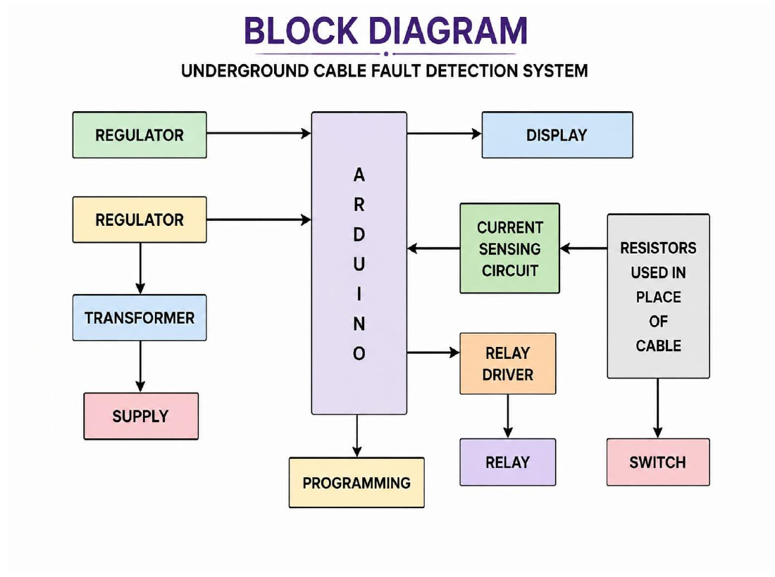
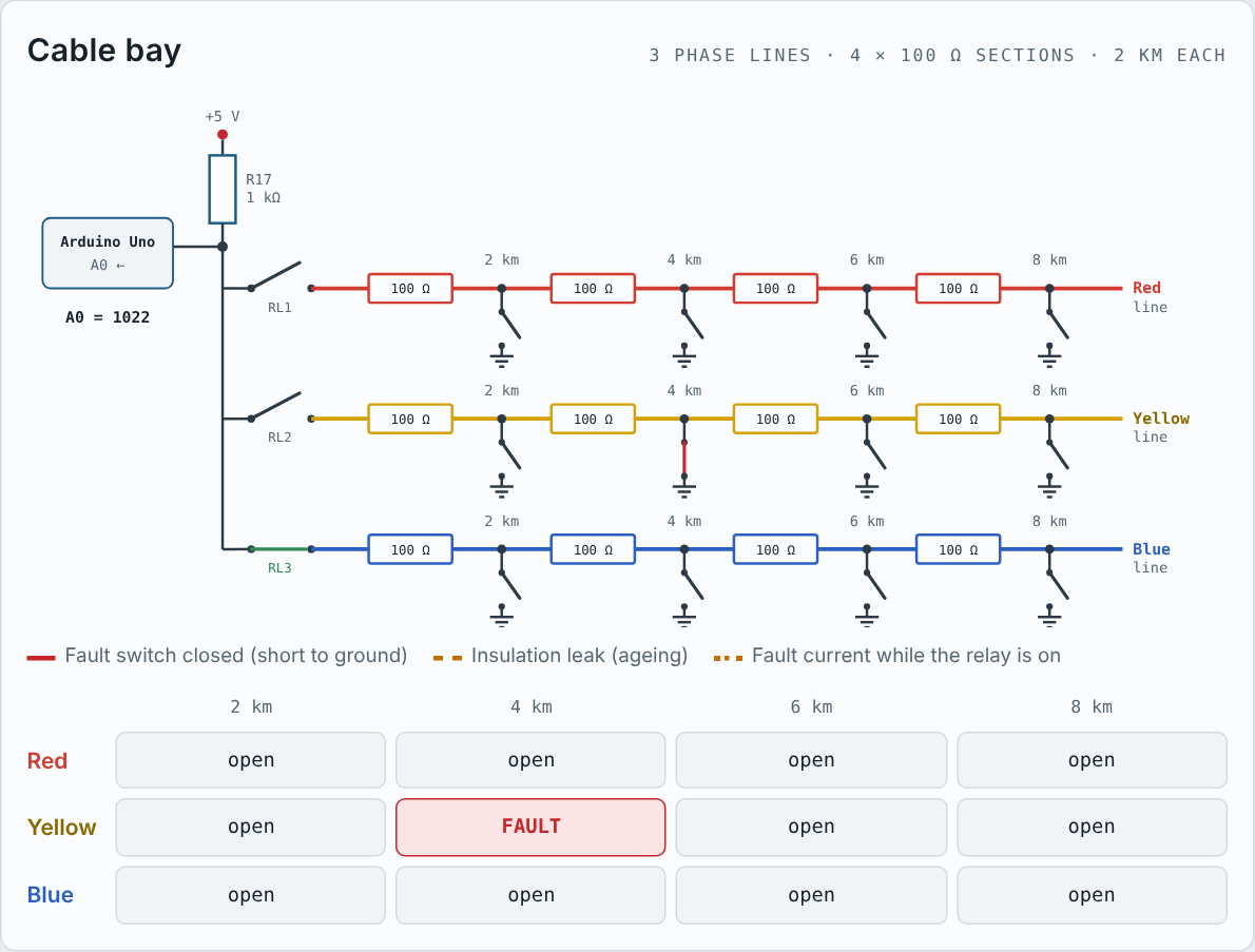
1. Cable model. Each of the three phase lines (Red, Yellow, Blue) is modelled with four 100 Ω resistors in series. Each resistor stands for a 2 km section, so the line covers 8 km. Switches between the sections create a fault: closing one shorts the line to ground at that point, like damaged insulation touching the earth.
2. Working principle (voltage divider). Resistor R17 (1 kΩ) connects the Uno’s 5 V supply to the cable under test. R17 and the cable resistance up to the fault form a voltage divider, and the Arduino reads the middle point on pin A0:
V_{A0} = 5\,\text{V} \times \frac{R_{cable}}{1\,\text{k}\Omega + R_{cable}}A farther fault puts more cable resistance in the path, so the voltage at A0 rises. With no fault, no current flows and A0 reads the full 5 V (3.3 V on the UNO Q).
| Fault at | Cable resistance | A0 on Arduino Uno (5 V) | A0 on UNO Q (3.3 V) | ADC reading (10-bit, 0–1023) |
|---|---|---|---|---|
| 2 km | 100 Ω | 0.45 V | 0.30 V | 93 |
| 4 km | 200 Ω | 0.83 V | 0.55 V | 171 |
| 6 km | 300 Ω | 1.15 V | 0.76 V | 236 |
| 8 km | 400 Ω | 1.43 V | 0.94 V | 292 |
| No fault | open circuit | 5.00 V | 3.30 V | 1023 |
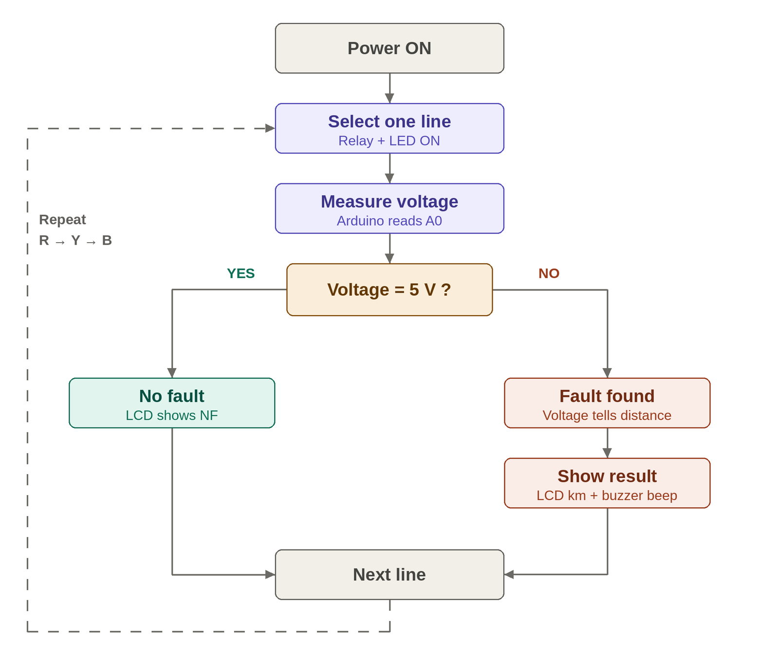
3. Scanning the lines. The Arduino Uno switches on one relay at a time through the ULN2003 driver (pins 8, 9 and 10). The matching LED lights to show which line is being tested. After 0.5 s for the relay to settle, the Arduino reads A0, converts the reading to a distance, and moves to the next line. A full Red → Yellow → Blue scan takes 3 s and repeats continuously.
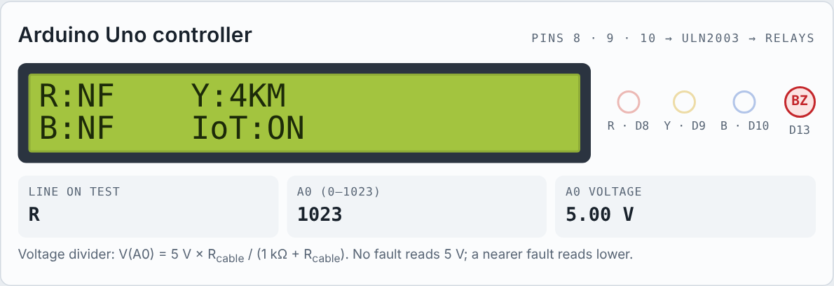
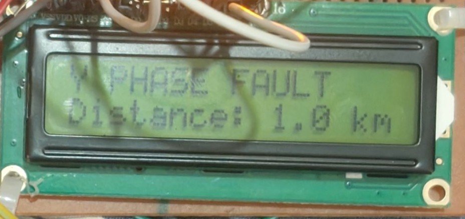
4. Display and alarm. The 16×2 LCD shows all three lines at once, for example R:NF Y:4KM and B:NF IoT:ON (NF = no fault). The buzzer beeps while any line has a fault.
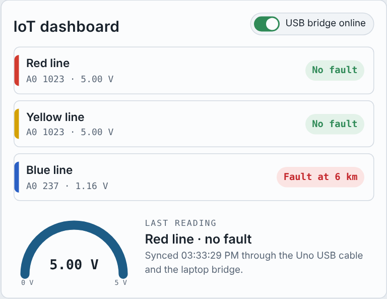
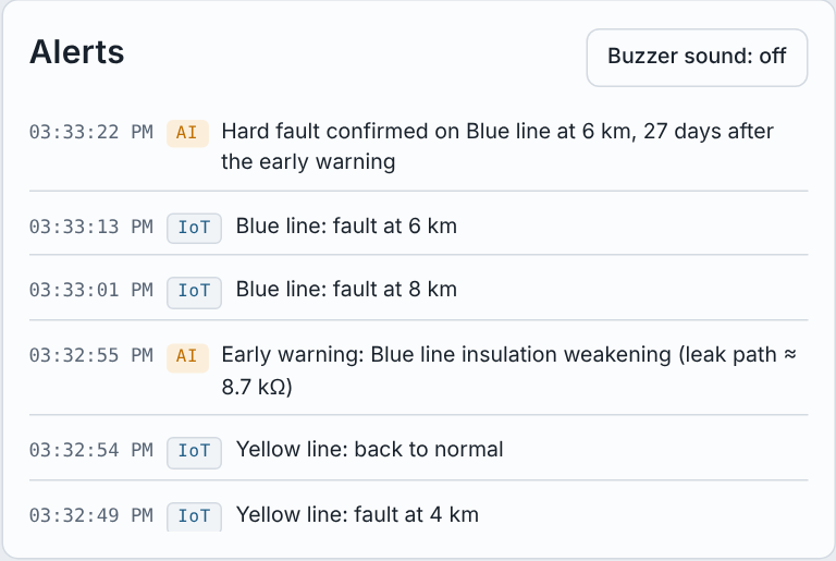
5. IoT. The Uno sends each result through its USB cable to a laptop running the Blynk serial gateway, which forwards it to the Blynk IoT cloud. The dashboard shows the status of each line, and Blynk sends a phone notification when a new fault appears. No Wi-Fi module or extra component is needed. On the UNO Q, the onboard Wi-Fi replaces the laptop.
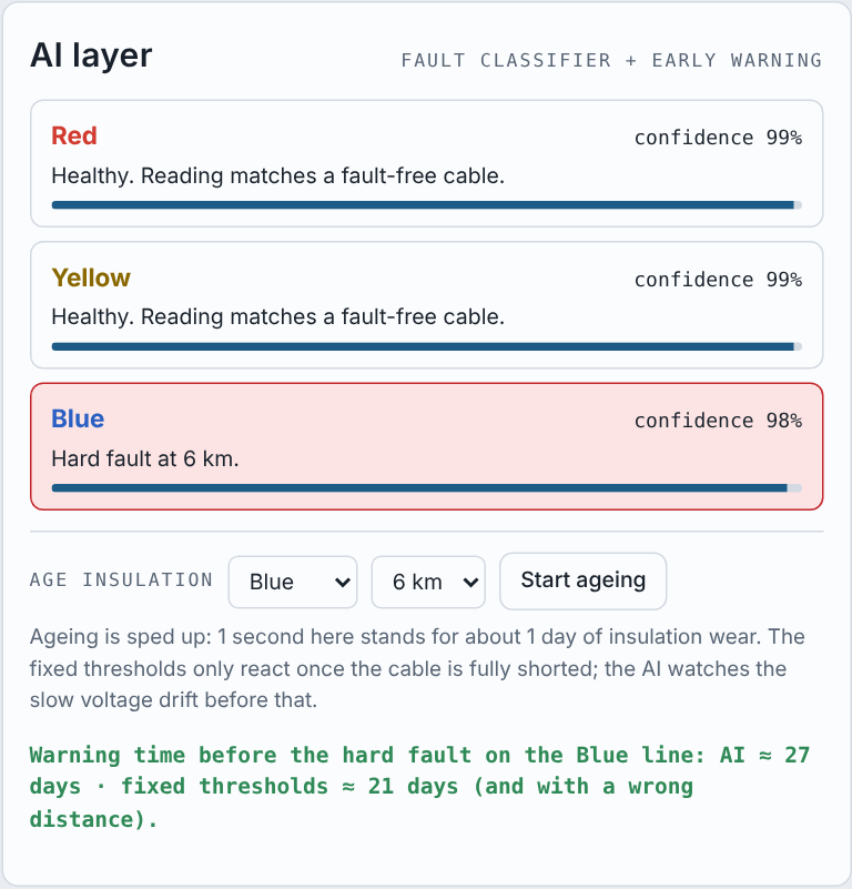
6. AI layer. Fixed thresholds only react once a cable is fully shorted. The AI layer adds a fault classifier with a confidence score and an early warning that watches the slow voltage drift caused by weakening insulation. In our digital twin, the AI warned about 27–30 days (simulated) before the hard fault, while the fixed thresholds reacted about 21 days before it and first showed the wrong distance. The AI layer is demonstrated in the digital twin; on the UNO Q it can run in Python on the board’s Linux processor.
Coding explanation and configuration
The firmware ( Cable_Fault_Blynk_Uno.ino ) runs on the Arduino Uno and compiles to 13 KB of the 32 KB flash and 554 bytes of the 2 KB RAM. On the UNO Q, the same sketch logic would run on the STM32U585 microcontroller, with the Blynk calls moved to a small Python app on the Linux side.
Libraries. In the Arduino IDE, open Sketch → Include Library → Manage Libraries, search for Blynk (by Volodymyr Shymanskyy) and click Install. LiquidCrystal is built into the IDE. Select Tools → Board → Arduino Uno and the correct COM port.
Code structure.
1. The top of the sketch holds the three Blynk lines (template ID, template name, auth token) copied from the Blynk console.
2. Pin setup matches the circuit: LCD on pins 2–7, relays and LEDs on pins 8, 9 and 10, buzzer on pin 13, sensing on A0.
3. distanceFromAdc() converts the A0 reading into a distance using thresholds placed halfway between the expected readings.
4. scanStep() runs every 500 ms without delay() : step one switches on a line’s relay, step two reads A0, updates the LCD and sends the result to Blynk.
5. sendToBlynk() updates the dashboard only when a line’s state changes and calls Blynk.logEvent() for the phone alert.
6. CALIBRATION_MODE 1 shows the raw A0 readings on the LCD so the thresholds can be checked on real hardware.
// A0 reading (0-1023) -> distance in km (R17 = 1k, 100 ohm per 2 km)
int distanceFromAdc(int adc) {
  if (adc > 650) return 0;      // no fault
  if (adc < 132) return 2;
  if (adc < 203) return 4;
  if (adc < 264) return 6;
  return 8;
}
// Step 1: switch on one line's relay + LED. Step 2 (0.5 s later): measure
it.
void scanStep() {
  if (!relayOn) {
    allLinesOff();
    digitalWrite(LINE_PIN[current], HIGH);
    relayOn = true;
    return;
  }
  rawAdc[current]  = readAdc();                 // average of 8 samples
  faultKm[current] = distanceFromAdc(rawAdc[current]);
  sendToBlynk(current);                         // dashboard + phone alert
  allLinesOff();
  relayOn = false;
  current = (current + 1) % 3;                  // Red -> Yellow -> Blue
  updateLcd();
}
Fig 3. Code snippet: distance conversion and line scanning
Because the USB serial port carries Blynk data, the sketch does not use Serial.print , and Serial Monitor must stay closed while the Blynk gateway runs. Blynk.config() is non-blocking, so fault detection on the LCD keeps working even when the laptop is disconnected.
IoT dashboard and digital twin
Blynk IoT dashboard setup. The dashboard needs no extra hardware: the Uno talks to Blynk through its USB cable and a laptop. On the UNO Q, the onboard Wi-Fi would make the laptop unnecessary.
1. On blynk.cloud, create a template “Cable Fault Detector” with hardware Arduino and connection Serial/USB.
2. Add datastreams on virtual pins:
| Virtual pin | Type | Shows |
|---|---|---|
| V0, V1, V2 | String | Status text of the Red, Yellow and Blue lines (“No Fault” or “Fault at 4 km”) |
| V3, V4, V5 | Integer 0–1 | Fault LED for each line |
| V6 | Integer 0–8, km | Distance of the line just tested |
3. Add an event with code cable_fault and turn on notifications, so a new fault reaches the phone.
4. Build the web and mobile dashboard: three Label widgets (V0–V2), three LED widgets coloured red, yellow and blue (V3–V5) and a Gauge (V6).
5. Add a device from the template and paste its three #define lines into the sketch. 6. Upload the sketch, close Serial Monitor, then run the gateway script from the Blynk library folder: blynk-ser.bat -c COM3 (use the Uno’s COM port). The LCD shows IoT:ON once connected.
Live digital twin. We built an interactive web simulation of the complete system, published on GitHub Page. Visitors close fault switches, watch the relays scan, read the LCD and A0 values, see the IoT dashboard and alerts, and run the insulation-ageing demo of the AI layer.
Connection explanation
All parts connect to the Arduino Uno as in the Proteus circuit; the table lists every connection.
| Part | Pin/terminal | Connects to |
|---|---|---|
| LCD 16×2 | RS, E, D4, D5, D6, D7 | Uno pins 2, 3, 4, 5, 6, 7 |
| LCD 16×2 | VSS, RW / VDD / VEE | GND / +5 V / wiper of RV1 (10 kΩ contrast) |
| ULN2003 | IN1, IN2, IN3 (1B, 2B, 3B) | Uno pins 10, 9, 8 (Blue, Yellow, Red line) |
| ULN2003 | OUT1–OUT3, COM | Relay coils RL1–RL3, +12 V |
| 1N4007 D1–D3 | Across each relay coil | Absorb the coil spike when a relay switches off |
| Relays RL1–RL3 | COM / NO contacts | Connect one cable line at a time to the sensing point |
| LEDs D4–D6 + R18–R20 (100 Ω) | Anode via resistor | Uno pins 8, 9, 10 (light with their line’s relay) |
| Buzzer BUZ1 | + / − | Uno pin 13 / GND |
| R17 (1 kΩ) | Top / bottom | +5 V (3.3 V pin on the UNO Q) / sensing point of the cable lines |
| Sensing point | — | Uno A0 |
| Cable model R1–R16 (100 Ω) | In series, 4 per line | Fault switches from each 2 km junction to ground |
| Power | 5 V / 12 V | Uno by USB / relay supply; all grounds common |
During assembly, connect all grounds together (Uno, ULN2003, 12 V supply). Mount the switches in a row per line so each one clearly marks 2, 4, 6 or 8 km.
On the UNO Q. The UNO Q header pins use 3.3 V logic, and A0–A5 must never see more than 3.3 V, so R17 connects to the 3V3 pin. The ULN2003 inputs switch reliably from 3.3 V, and the LCD stays powered from 5 V with RW tied to GND, so no 5 V signal reaches the UNO Q pins.
Testing
We tested the circuit in Proteus 8 and in the digital twin by closing fault switches one by one and checking the LCD, LEDs, buzzer and dashboard.
1. Check every connection, especially the common ground and the relay supply, before powering on.
2. Power the Uno over USB and the relays from 12 V. With all switches open, the LCD mustshow R:NF Y:NF / B:NF .
3. Close one switch at a time and confirm the distance on the LCD. Open it again before testing the next one.
4. Set CALIBRATION_MODE 1 once on real hardware to read the raw A0 values; adjust the thresholds if relay contact resistance shifts them.
5. Run the Blynk gateway and check that the dashboard and the phone alert match the LCD.
| Test | Expected LCD | Buzzer | Dashboard |
|---|---|---|---|
| All switches open | R:NF Y:NF B:NF | Off | All lines “No Fault” |
| Yellow switch at 4 km | Y:4KM | Beeping | Yellow “Fault at 4 km” + phone alert |
| Red at 2 km and Blue at 8 km | R:2KM, B:8KM | Beeping | Two faults + two alerts |
| USB / laptop disconnected | Results continue, IoT:– | As above | Shows last synced data |
Schematics
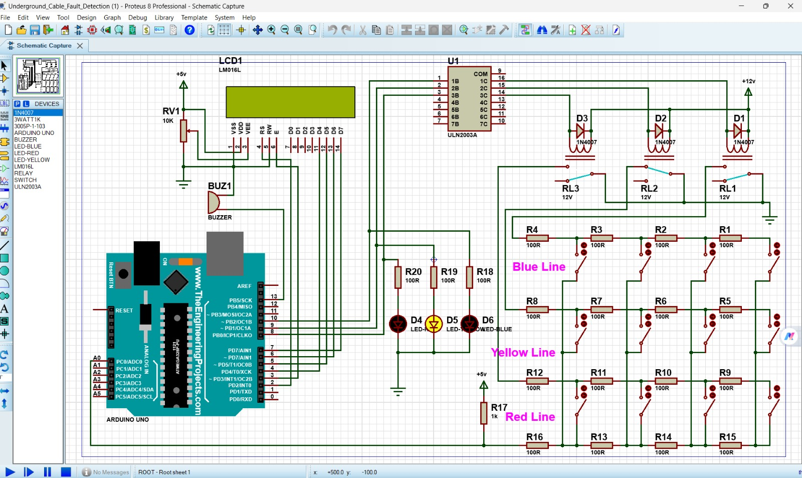
The schematic uses the Arduino UNO part in Proteus. On the UNO Q, R17 connects to 3.3 V instead of 5 V; all other pins stay the same.
Project video and Source Code
Download Source Code and Watch Demo Videos
Upload Cable_Fault_Blynk_Uno.ino to this repository so the link carries the Arduino code as well as the live simulation.
