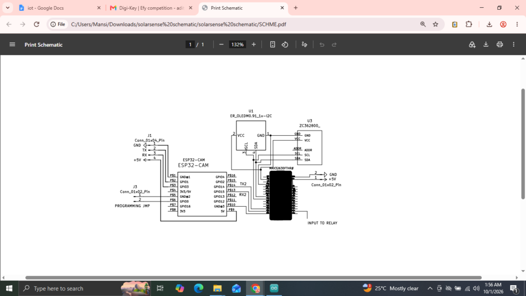
SolarSense AI: An AIoT-Based Predictive Solar Panel Cleaning and Inverter Monitoring System is an intelligent solar-maintenance solution designed to improve cleaning efficiency by combining camera-based AI analysis, live inverter monitoring, environmental sensing, and automated cleaning control. Unlike conventional timer-based cleaning systems, SolarSense AI uses a new AI analysis result to determine whether the observed panel condition warrants a cleaning operation, helping avoid unnecessary cleaning cycles while supporting improved solar-panel maintenance.
The system uses the MAX32630FTHR as the primary embedded control and data-fusion unit, while an ESP32-CAM handles image capture, Wi-Fi connectivity, the web and Progressive Web App (PWA) interface, and Bluetooth communication with a Polycab solar inverter. The ESP32-CAM communicates with the inverter through its proprietary FF10 Bluetooth Low Energy (BLE) service, using FF11 for command writing and FF12 for receiving notifications. It parses incoming inverter packets and forwards the latest operating data to the MAX32630FTHR. Monitored parameters include solar input, inverter power, voltage, current, energy generation, active power, peak power, and inverter temperature.
The MAX32630FTHR receives inverter telemetry and AI-analysis information over UART, maintains the latest system state, reads ambient illumination using a BH1750 light sensor, updates an SSD1306 OLED display, and controls the cleaning relay. A key architectural feature is the separation of continuous inverter status updates from new AI-analysis decisions. This allows the system to refresh monitoring information without automatically initiating cleaning whenever a status message arrives. Instead, cleaning control is based on the designated AI decision and the system’s local control logic.
By integrating solar-inverter telemetry, visual assessment, embedded decision-making, and automated actuation, SolarSense AI provides a foundation for predictive and condition-based solar-panel maintenance. The system aims to reduce unnecessary cleaning operations, improve maintenance planning, and provide operators with clearer visibility into solar-system performance. Field testing across different dust levels, weather conditions, panel orientations, and inverter operating states will be necessary to validate the accuracy of the AI analysis, cleaning decisions, and resulting energy-generation benefits.
Component List:
| S. No. | Component / Part | Manufacturer | Part Number | Qty. | Primary Function |
|---|---|---|---|---|---|
| 1 | MAX32630FTHR | Analog Devices / Maxim Integrated | MAX32630FTHR# | 1 | Main embedded controller and edge data-fusion node |
| 2 | 0.96-inch OLED | DLC Display Co., Ltd. | DLC0096DNOG-W-10 | 1 | Local system-status display |
| 3 | ESP32-CAM 8 MB | Olimex LTD | ESP32-CAM-8MB | 1 | Camera, Wi-Fi, web/PWA gateway and inverter BLE gateway |
| 4 | BH1750FVI ambient-light sensor | ROHM Semiconductor | BH1750FVI-TR | 1 | Ambient-light/lux measurement |
| 5 | JST-PH 2-pin jumper cable | Adafruit Industries | 4714 | 4 | Prototype interconnection |
| 6 | JST 04KR cable | JST Sales America | A04KR04KR26E51A | 2 | Prototype interconnection |
| 7 | PAN1326B | Panasonic | PAN1326B | 1 | BLE/HCI interface evaluated for MAX-side wireless integration |
| 8 | 5 V relay module | — | Prototype module | 1 | Cleaning actuator control |
Procurement BOM Snapshot (DIGIKEY MYLIST)
| Part | Qty. | Unit Price (USD) | Extended Price (USD) |
|---|---|---|---|
| MAX32630FTHR# | 1 | 45.85 | 45.85 |
| DLC0096DNOG-W-10 OLED | 1 | 33.41 | 33.41 |
| ESP32-CAM-8MB | 1 | 15.97 | 15.97 |
| BH1750FVI-TR | 1 | 3.42 | 3.42 |
| Adafruit 4714 jumper cable | 4 | 0.95 | 3.80 |
| JST A04KR04KR26E51A | 2 | 1.02 | 2.04 |
| Subtotal of listed spreadsheet items | 104.49 |
Project Explanation Step By Step :
SolarSense AI is an AIoT-based predictive solar-panel cleaning system designed to combine solar-inverter monitoring, camera-based AI analysis, environmental sensing, embedded data processing and automatic cleaning control. The system is built around the MAX32630FTHR as the main embedded control and data-fusion node, while an ESP32-CAM provides the camera, Wi-Fi/PWA interface and Bluetooth communication gateway for the Polycab solar inverter.
Unlike a conventional solar-panel cleaning system that operates only on a fixed timer, SolarSense AI uses a new AI analysis result to determine whether the panel condition should initiate cleaning. At the same time, the system continuously receives live inverter parameters such as solar input, inverter power, voltage, current, energy generation, active power, peak power and inverter temperature.
The overall system is divided into two major embedded sections. The first section is the ESP32-CAM. It captures images, provides Wi-Fi connectivity and web/PWA endpoints, communicates with the Polycab inverter over BLE, parses inverter packets and forwards the latest information to the MAX32630FTHR. The ESP32-CAM firmware uses the Polycab inverter’s proprietary FF10 BLE service, with FF11 used for writing commands and FF12 used for receiving notifications.
The second section is the MAX32630FTHR. It receives the inverter and AI information over UART, maintains the latest system state, reads the BH1750 ambient-light sensor, updates the SSD1306 OLED display and controls the cleaning relay. The MAX32630FTHR therefore acts as the local decision and actuator-control unit.
A key feature of the architecture is the separation between continuous inverter STATUS information and a new AI ANALYSIS decision. STATUS messages are used only to update live monitoring values and do not trigger cleaning. A new ANALYSIS message contains the latest AI dust decision and is the event that can change the cleaning state. This prevents an old AI decision from being repeatedly applied every time new inverter telemetry is received.
The system also provides a MANUAL_CLEAN command. This allows the operator to initiate cleaning directly from the PWA/web interface without waiting for a new AI analysis.
The MAX32630FTHR provides a local OLED interface showing solar information, energy information and the cleaning state. A BH1750 sensor measures ambient light and the MAX sends its latest lux value together with relay state as feedback to the ESP32-CAM.
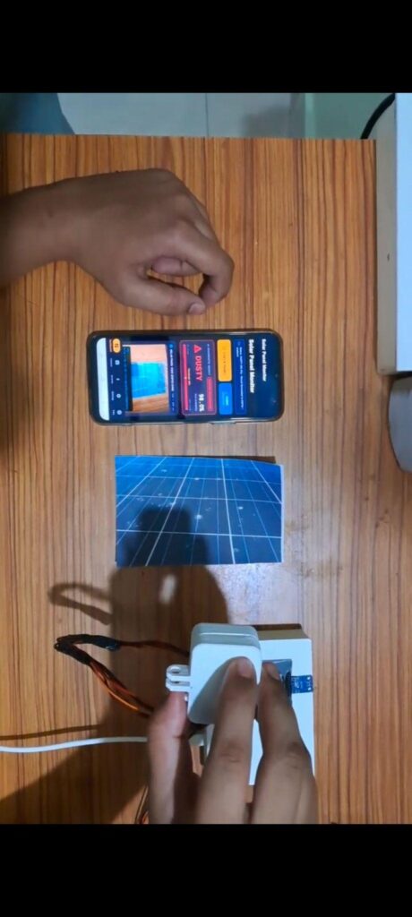
Coding Explanation and Configuration
The project uses two main firmware programs: one for the ESP32-CAM and one for the MAX32630FTHR.
ESP32-CAM Firmware
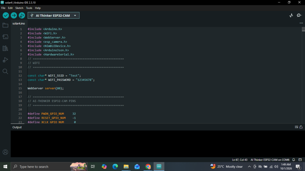
The ESP32-CAM firmware provides the camera, Wi-Fi, web server, BLE and MAX32630FTHR UART interface. The main software components(library) include:
`WiFi.h` for network connectivity.
`WebServer.h` for the HTTP/PWA interface.
`esp_camera.h` for camera initialization and image capture.
`NimBLEDevice.h` for Bluetooth Low Energy communication with the Polycab inverter.
`ArduinoJson.h` for JSON processing.
`HardwareSerial.h` for UART communication with the MAX32630FTHR.
The camera is configured for a 640 × 480 frame. The firmware provides HTTP interfaces for image capture, image retrieval, inverter information, status, AI analysis, manual cleaning and MAX feedback.
Polycab Inverter BLE Configuration
The ESP32-CAM connects to the Polycab inverter using BLE.
The implemented BLE structure is:
| Item | Configuration |
|---|---|
| Service | `0000FF10-0000-1000-8000-00805F9B34FB` |
| Write characteristic | `0000FF11-0000-1000-8000-00805F9B34FB` |
| Notify characteristic | `0000FF12-0000-1000-8000-00805F9B34FB` |
| BLE stack | NimBLE |
| Inverter role | BLE peripheral / server |
| ESP32-CAM role | BLE central / client |
Two request frames are implemented by the ESP32-CAM:
REQ_ETODAY = 01 03 10 21 00 1D D1 09
REQ_SI = 01 03 10 01 00 20 11 12
The received notification packets are classified using the packet type byte. The energy packet is parsed separately from the instantaneous-data packet.
The instantaneous-data parser extracts:
L1 voltage
L1 current
inverter power
solar input
inverter temperature
active power
The energy parser extracts:
energy generated today
total energy generated
peak power
MAX32630FTHR Firmware
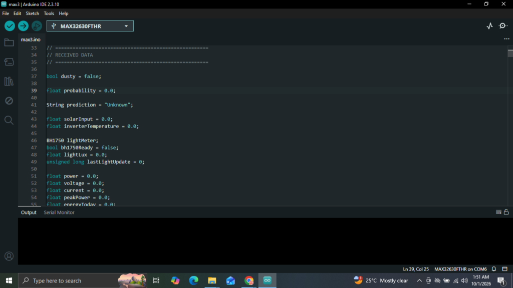
The MAX32630FTHR firmware is responsible for local processing and control.
The current implementation uses:
`Wire2` for the I²C2 peripheral bus.
BH1750 at address `0x23`.
SSD1306 OLED at address `0x3C`.
UART2 for communication with the ESP32-CAM.
P3_5 as the relay-control output.
The OLED uses:
SDA = P5_7
SCL = P6_0
Address = 0x3C
The BH1750 uses:
I2C2
Address = 0x23
Mode = CONTINUOUS_HIGH_RES_MODE
The ESP32-CAM/MAX32630FTHR UART connection is:
ESP32-CAM GPIO13 TX → MAX32630FTHR P3_0 RX
ESP32-CAM GPIO14 RX ← MAX32630FTHR P3_1 TX
GND ↔ GND
The MAX firmware receives newline-delimited JSON frames and stores the latest operating values.
UART JSON Communication
The communication between the ESP32-CAM and MAX32630FTHR is intentionally divided into three command types.
1. STATUS
STATUS is periodically sent by the ESP32-CAM and carries live inverter information.
{
“cmd”:”STATUS”,
“power”:420.0,
“voltage”:231.0,
“current”:1.82,
“energy_today”:12.5,
“energy_total”:1520.4,
“temperature”:34.2,
“solar_input”:450.0,
“active_power”:418.0,
“peak_power”:450.0
}
The MAX32630FTHR updates the live inverter values when STATUS is received. STATUS does not change the stored AI dust decision and does not start cleaning.
2. ANALYSIS
ANALYSIS is sent only when a new AI result is available.
{
“cmd”:”ANALYSIS”,
“dusty”:true,
“probability”:0.89673,
“prediction”:”Dusty”,
“power”:420.0,
“voltage”:231.0,
“current”:1.82,
“energy_today”:12.5,
“energy_total”:1520.4,
“temperature”:34.2,
“solar_input”:450.0,
“active_power”:418.0,
“peak_power”:450.0
}
The ESP32-CAM takes the new AI result supplied by the PWA and adds the latest inverter values before sending the combined message to the MAX32630FTHR.
3. MANUAL_CLEAN
The manual command is:
{
“cmd”:”MANUAL_CLEAN”
}
When received, the MAX32630FTHR immediately starts the cleaning routine.
AI Decision and Relay Control
When the MAX32630FTHR receives a new ANALYSIS message, it updates the AI state.
The decision flow is:
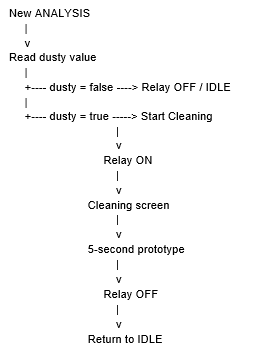
The current prototype uses a 5-second cleaning interval. This value is intended for prototype demonstration and should be calibrated against the actual cleaning mechanism for a final deployment.
OLED Display Configuration
The SSD1306 OLED provides three main display states:
Solar Screen
Displays the primary solar-system information, including the current AI/dust state, PV power and inverter temperature.
Energy Screen
Displays:
Energy generated today.
Total energy generated.
Cleaning Screen
Displays:
Cleaning state.
Dust/AI information.
Cleaning/wait indication.
The OLED screen changes automatically during normal operation and remains on the cleaning screen while cleaning is active.
APP / PWA Making
The ESP32-CAM provides the web/PWA interface used to interact with the system.
The implemented HTTP endpoints include:
| Endpoint | Method | Purpose |
|---|---|---|
| `/` | GET | Main web interface |
| `/capture` | GET | Capture a new camera image |
| `/image` | GET | Provide the latest image |
| `/inverter` | GET | Provide inverter information |
| `/status` | GET | Provide current system status |
| `/analysis` | POST | Submit a new AI analysis |
| `/clean` | GET/POST | Request manual cleaning |
| `/max` | GET | Read MAX32630FTHR feedback |
The `/analysis` endpoint is particularly important. The PWA sends the new AI result to the
ESP32-CAM, which then combines it with the latest inverter information and forwards the resulting ANALYSIS message to the MAX32630FTHR.
The `/clean` endpoint sends the MANUAL_CLEAN command.
The `/max` endpoint exposes the latest feedback received from the MAX32630FTHR, including the measured light level and relay state.
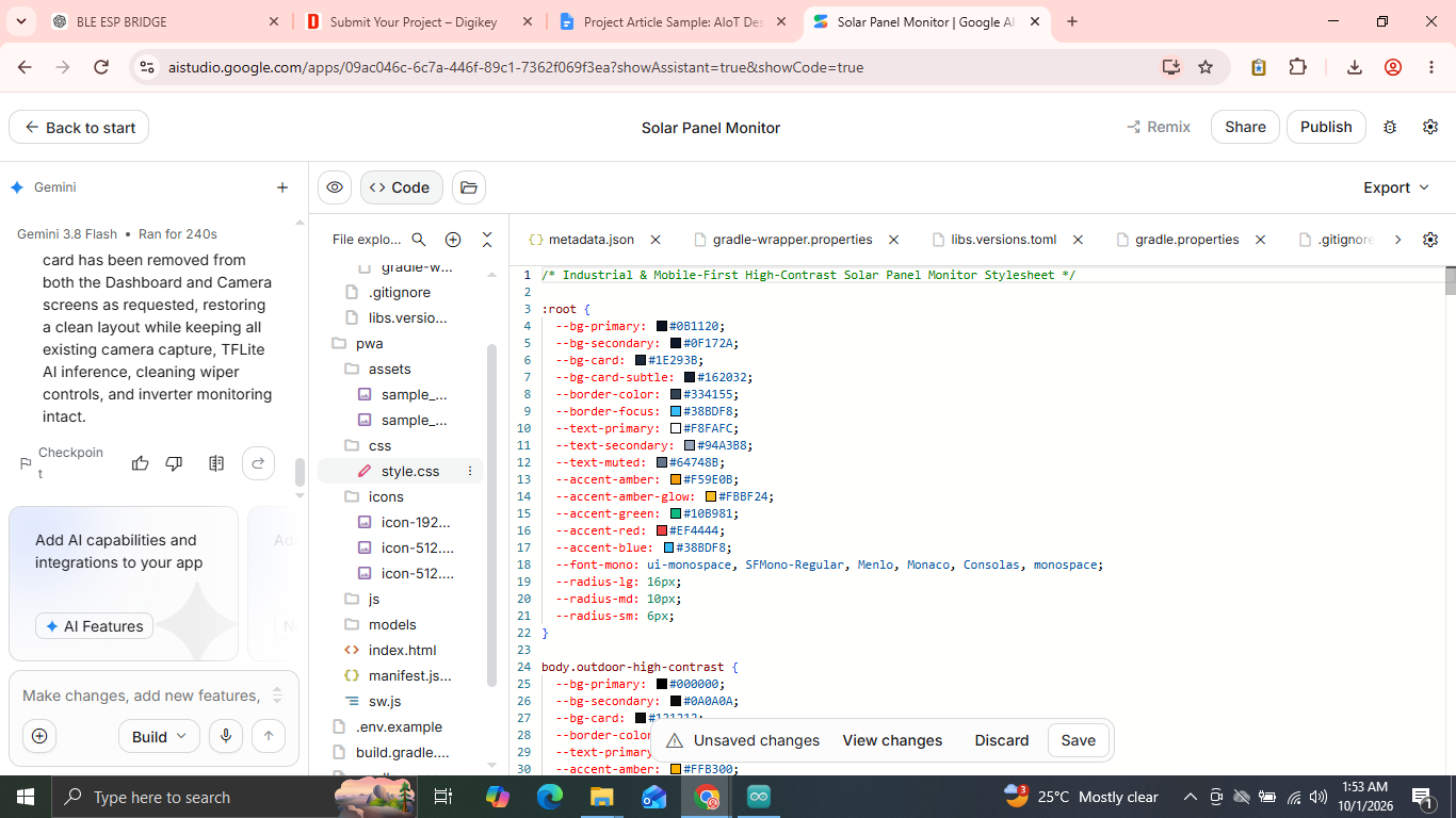
App Screen and Working
Step 1: Configure Your ESP32 IP
1. Tap the Settings tab in the bottom navigation bar.
2. In ESP32-CAM IP / Base URL, enter your ESP32’s local network address (e.g., http://10.104.65.172 or your router’s assigned IP).
3. Tap Test Connection to verify latency and camera status (GET /status).
(If hardware is currently unpowered or off-grid, turn on Demo Mode to test the entire UI flow).
Step 2: Live MAX32630FTHR Feedback (/max)
- The app automatically polls
GET http://<ESP32-IP>/maxin the background every 1.5 seconds. - Light Level: Real ambient lux measurement displayed directly as:
Light: 22.5 lux
- Relay State: Displays the current relay position (
ONin green,OFFin slate/amber). - If the microcontroller temporarily loses signal, the app preserves the last valid measurement with an
OFFLINE (Cached)badge until the connection automatically resumes.
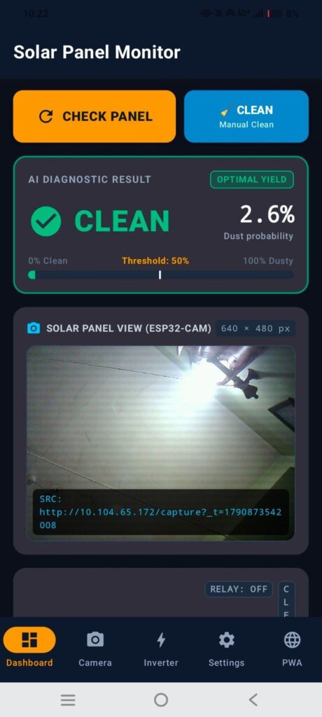
Step 3: Run Dust AI Inspection (“CHECK PANEL”)
1. Tap the prominent CHECK PANEL button on the Dashboard or Camera tab.
2. The app:
- Requests a pristine, uncompressed snapshot from
GET /capture. - Displays the high-resolution frame in the viewport.
- Feeds the normalised tensor (
512 × 512 × 3) into the local on-device
TensorFlow Lite engine.
- Evaluates soiling vs. the configured threshold (default
50%).
3. If dusty, the result automatically posts to POST /analysis to notify your hardware controller.
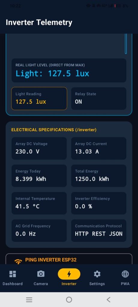
Step 4: Monitor Inverter Performance (/inverter)
1. Switch to the Inverter tab.
2. View real electrical metrics directly from GET /inverter:
- Active Power Generation (W)
- DC Array Voltage & Current (V / A)
- Daily & Lifetime Yield (kWh)
- Inverter Heatsink Temperature (e.g.
39.8 °C, separate from the MAX board) - Grid Frequency & Conversion Efficiency
Step 5: Manual Wiper Cleaning (/clean)
- Tap 🧹
MANUAL CLEANon either the Dashboard, Camera, or Settings tab. - Sends an immediate command to
POST http://<ESP32-IP>/cleanto activate the cleaning actuator or wiper system.
Step 6: Load Any Custom .tflite Model (Optional)
- Go to the Settings tab
- TFLite Model Specifications.
- Tap Upload Custom .tflite File to select your own custom-trained model file from your device storage to run directly inside the local engine.
Connection Explanation
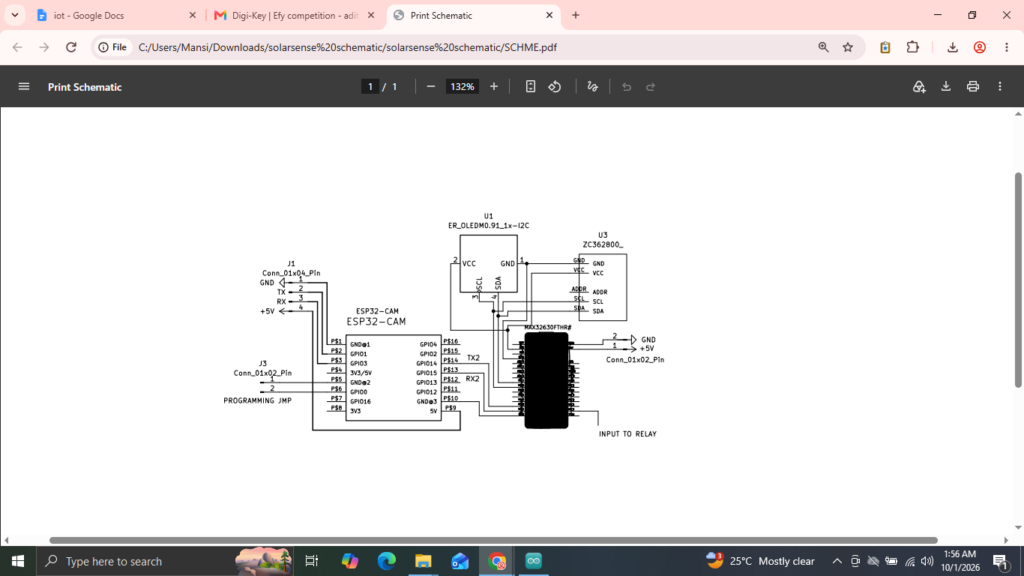
The complete prototype is connected as follows.
ESP32-CAM to MAX32630FTHR
| ESP32-CAM | MAX32630FTHR | Function |
|---|---|---|
| GPIO13 TX | P3_0 RX | JSON data from ESP32-CAM to MAX |
| GPIO14 RX | P3_1 TX | Feedback from MAX to ESP32-CAM |
| GND | GND | Common ground |
OLED
| OLED | MAX32630FTHR |
|---|---|
| SDA | P5_7 |
| SCL | P6_0 |
| VCC | Appropriate supply |
| GND | GND |
| Address | 0x3C |
BH1750
The BH1750 is connected to the same I²C2 bus as the OLED.
MAX32630FTHR I2C2
|
+—- SSD1306 OLED (0x3C)
|
+—- BH1750 (0x23)
Because the two devices have different I²C addresses, they can share the same bus.
Relay
The current MAX32630FTHR firmware uses:
MAX32630FTHR P3_5 → Relay IN
Relay GND → MAX GND
Relay VCC → Suitable 5 V supply
Relay COM/NO → Cleaning actuator/load
The relay must be powered from an appropriate supply and the GPIO should only provide the control signal. For mains-powered loads, proper isolation, enclosure, fuse/protection and safe wiring practices are required.
Polycab Inverter
The Polycab inverter is connected wirelessly to the ESP32-CAM through BLE. The ESP32-CAM acts as the BLE gateway and forwards the relevant inverter parameters to the MAX32630FTHR through UART.
PAN1326B
The PAN1326B was evaluated as the Bluetooth HCI interface for MAX32630FTHR-side wireless integration. The operational inverter BLE gateway in the current prototype is the ESP32-CAM.
Testing
Before testing the complete system, each subsystem should be verified individually.
1. Power and Initialisation Test
Power the MAX32630FTHR and verify that:
OLED initialises.
BH1750 is detected.
UART communication starts.
Relay initialises in the OFF state.
2. BH1750 Test
Check that the BH1750 produces a valid lux value at address `0x23`.
Example feedback:
{
“light_lux”:22.5,
“relay”:”OFF”
}
3. OLED Test
Verify that the Solar, Energy and Cleaning screens are displayed correctly.
4. Inverter BLE Test
Power the Polycab inverter and verify that the ESP32-CAM connects to the FF10 service and receives FF12 notifications.
Verify the extracted parameters:
Solar input
Inverter power
Voltage
Current
Active power
Peak power
Temperature
Energy today
Total energy
5. STATUS Test
Verify that the ESP32-CAM periodically sends STATUS frames.
The MAX32630FTHR should update the displayed/available inverter data but should not start cleaning because of STATUS alone.
6. AI ANALYSIS Test
Submit a new AI analysis with:
“dusty”:true
The MAX32630FTHR should:
1. Update the AI state. 2. Display the dust/cleaning condition. 3. Activate the relay. 4. Keep the cleaning display active. 5. Complete the prototype cleaning interval. 6. Turn the relay OFF. 7. Return to normal operation.
7. Clean Condition Test
Submit:
“dusty”:false
The relay should remain OFF and the system should stay in the normal monitoring state.
8. Manual Cleaning Test
Send:
{“cmd”:”MANUAL_CLEAN”}
The MAX32630FTHR should immediately execute the cleaning routine.
9. Feedback Test
Verify that the ESP32-CAM receives:
{“light_lux”:22.5,”relay”:”ON”}
and exposes the latest MAX status through the `/max` endpoint.
Schematics