
The extremely high theoretical energy density of lithium-air batteries encourages researchers to develop commercially viable batteries. However, the gap between idea and reality is still big. The challenge lies in improving the cycling stability under complex superoxide/peroxide containing situations while keeping a good energy efficiency and rate capability. The batteries are undergoing high-speed development and admirable breakthrough in improving their electrochemical performance.
The lithium-air battery (LAB) is a metal-air electrochemical cell which during discharge oxidises lithium metal at the anode and reduces oxygen from air at the cathode to induce a current flow. The process can be reversed by applying an external potential and such a battery can be electrically recharged. Because oxygen can be supplied continuously from air rather than stored in finite amounts within the cell, lithium-air batteries can theoretically provide an energy density ten times that of conventional lithium-ion batteries. But there are hurdles to overcome.
In the course of last decade, great attention has been devoted by many top academic and industrial laboratories worldwide, which now has yielded solutions to some of the hurdles. To make lithium-air battery technology commercially viable, two goals are highly important: a suitable cathode that uses a highly active and stable catalyst to enhance oxygen reduction reaction (ORR) and oxygen evolution reaction (OER) kinetics and a proper electrolyte design.
In the quest for finding a highly active catalyst, scientists have developed efficient catalysts like nanolithia, trimolybdenum phosphide, lithium iodide, etc. New electrolyte formulations have been developed that significantly reduce side reactions in the battery chemistry to enable longer cycle stability. Improved air-cathode structure with nanocarbon-containing catalyst increases the practical energy density.
With all these improvements the resulting battery works in the laboratory with high energy efficiency of 90%, an energy density of about 1500Wh/kg (about eight times better than Li-ion battery), and a long cycle life of 1000. PolyPlus Battery Company is now planning to launch world’s first commercial lithium-air battery in the USA.

One of the bottlenecks in widespread implementation of sustainable energy technologies is a highly-efficient energy storage system. Lithium-ion batteries with energy capacity of 100 to 265Wh/kg are the prevailing solution for today’s electrical and electronic devices. Various research studies now show that lithium-air batteries have the potential to reach an estimated energy density of 1300Wh/kg in future and about 500Wh/kg immediately in sight.
Energy density
Lithium-air batteries are often considered the ultimate batteries due to their theoretical energy density, which is many times more than of traditional lithium-ion batteries, making them comparable to gasoline. This is because the batteries utilise ambient oxygen and most of the cell volume is occupied by the anode while the cathode-active material is not stored in the battery. Lithium metal is a tempting anode material for any battery because of its outstanding specific capacity (3842mAh per gram against 815mAh per gm for zinc).
Lithium-air batteries have the potential to revolutionise the clean energy industry. They may enable electric cars to run on a battery that’s a fifth of the cost and a fifth of the weight of batteries at present available in the market, allowing a car to travel from Delhi to Allahabad, just about 650 km, on a single charge. Today an electric car can run about 300km per charge.
Energy density, that is, the energy that can be extracted from various energy storage materials, is shown in Table 1.
| Table 1 | ||
| Energy From Some Energy Storage Materials | ||
| Theoretical Energy Density (Wh kg–1) | Practical Energy Density (Wh kg–1) | |
| Gasoline | 12,889 | 1300 |
| Lead-acid battery | 170 | 20-40 |
| Ni-Cd battery | – | 45-80 |
| Ni-metal hydride battery | – | 60-120 |
| Li-ion battery | – | 100-265 |
| Li-air battery | 3500 | 1300 |
Due to engine inefficiency and heat loss, gasoline is predicted to have a practical lower energy density of 1300Wh kg–1 (wastes 70-88% energy). Lithium metal is very light. Li-air battery has a theoretical energy density of 12,000Wh kg–1, excluding the oxygen mass. Accounting for the weight of the battery pack, theoretical energy density may reach 3500Wh kg–1 for lithium-air battery.
Although energy density is very high, there are practical challenges impeding the development of lithium-air batteries. Previous attempts to develop a practical battery have resulted in low efficiencies and poor performance. However, continuous research work has now yielded a good lithium-air battery in the laboratory, which is about 90% efficient and can be recharged about 1000 times, reaching the end of the tunnel for commercial production.

Technical challenges
There are many challenges to commercially produce lithium-air batteries. Some of these are described below.
- A major challenge is the presence of moisture and carbon-dioxide (CO2) in the air, which significantly reduce the cell performance due to their strong affinity with lithium metal. The reaction of lithium with oxygen yields solid lithium-peroxide (Li2O2) on the cathode (positive electrode) of the battery. Due to low solubility of Li2O2 in organic electrolyte, it quickly precipitates out of the solution as crystals. These are sometimes deposited in great quantities at the cathode, resulting in sudden death of the cell.
- Lithium metal on the anode forms dendrites (microscopic fibres of lithium metal), which short-circuit electrical path, and sometimes get electroplated and react with the electrolyte, etc.
- Lithium metal, besides oxygen in the air, reacts with other components of air like nitrogen, CO2, and water vapour. To get a practical system, it becomes imperative to use filtration to get rid of the other components. The nonaqueous system requires air-purification to reduce water and CO2 content. But no acceptable purification system for EVs has so far been developed. However, aqueous lithium-air batteries can operate in the atmosphere because the discharge products are highly soluble in the catholyte.
- The lithium anode and the aqueous electrolyte of aqueous lithium-air batteries should be separated by a water-stable lithium-conducting solid electrolyte with high mechanical strength, because lithium metal reacts violently with water. The NASICON (lithium superionic conductor) type solid electrolytes are extensively used. But these become unstable on coming in contact with lithium metal. So, a lithium-conducting electrolyte is used as a buffer layer between lithium anode and the solid electrolyte. The disadvantage of the aqueous system is that the weight and volume of the solid electrolyte separator can reduce the specific energy density of the cell significantly.
- There is difficulty in getting the reaction that forms the solid product lithium peroxide to work reversibly.
- The efficiency is low due to the fact that the difference between discharge and charge voltage is very large, causing lot of energy loss during charging and discharging process.
- Lithium-air battery using solid-state electrolyte is attractive with respect to safety issues and long-term stability. But stable and dendrite formation-free lithium-ion conducting solid electrolytes are yet to be developed. Hence, a lithium stabilising interlayer, such as a liquid or a polymer electrolyte, is used in lithium-air batteries having solid electrolyte. Further, the cell capacity is dependent on the structure of the air electrode.
- Power cannot be drawn very fast out of the battery.
Solution
Some solutions to the problems mentioned above are:
-
Solid lithium-peroxide is a very bad electron conductor. It clogs the cathode pores and reduces the reversible reaction. The problem can be solved by adding lithium iodide as electrolyte additive to help break up the solid discharge product to form lithium hydroxide. As lithium hydroxide is soluble, it would not block the active carbon surface that generates the supply voltage.
-
Organic polymer electrolyte is used, which is mechanically stable as well as a good ionic conductor. The mechanical hardness of the polymer segment inhibits electrical shorting due to dendrite formation.
-
Researchers sometimes use redox mediators—molecules that go into a solution and help the reaction process. It brings down the difference between the charge and discharge to its lowest value to date of only 0.2V. So, battery can be made with 90% efficiency.
-
Protective layers are used on the anode so that lithium metal does not react with other components of air.
-
Sometimes the lithium-air battery is simply charged and discharged for a few cycles in a pure CO2 atmosphere when a dense mesh of lithium-carbonate crystals is formed on the surface of lithium anode, which acts as a filter and prevents the migration of water (H2O), oxygen (O2), CO2, and nitrogen to lithium anode, but allows lithium ions to move in the electrolyte selectively. So, unwanted side reactions are prevented.
-
By using special cathode made from molybdenum-di-sulphide, a thin film of lithium-peroxide is formed on cathode surface during normal operation, which is inert and protects the cathode from unwanted reaction. In this way batteries can be recharged 750 times.
-
In 2018, a new concept envisaged embedding nano compounds of lithium-oxides in a sponge-like lattice of cobalt-oxide, called nanolithia, as shown in Fig. 2. The nanolithia particles of lithium and oxygen are generally very unstable. But these particles become stable when housed in a cobalt-oxide matrix and, surprisingly, the aggregate acts as a fine catalyst to speed up the chemical reaction. In this variant the same kind of electrochemical reaction takes place between lithium and oxygen during charging and discharging but without letting the oxygen revert to its gaseous form. The bound oxygen in nanolithia does the job. In lithium-air batteries the voltage difference between charging and discharging is 1.3V, which reduces the charging efficiency. Use of nanolithia reduces the voltage loss from 1.3V to 0.24V. So, only 8% of electrical energy is turned to heat, resulting in the upgradation of charging efficiency to about 90%.
Fig. 2: Nanolithia particles of lithium-oxides shown in yellow in red cobalt-oxide lattice
Originally proposed in the 1970s as a possible power source for battery electric vehicles, the risk-to-benefit ratio was perceived as too high to pursue the new technology. Nevertheless, due to absence of other alternatives to high specific energy rechargeable batteries, and due to some initial promising results from laboratories, lithium-air batteries recaptured scientific interest late in the first decade of the 2000s and also due to advances in material sciences.
Electrochemistry
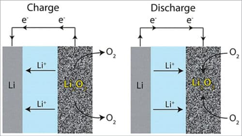
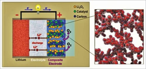
A lithium-air cell creates voltage from the availability of oxygen molecules at the positive electrode. Oxygen reacts with the positively charged lithium ions to form lithium-peroxide (Li2O2) and generates electricity. Electrons are drawn out of the electrode and such a battery is empty (discharged) if no more Li2O2 can be formed. The battery is fully discharged when all the pores of the cathode are filled up with Li2O2.
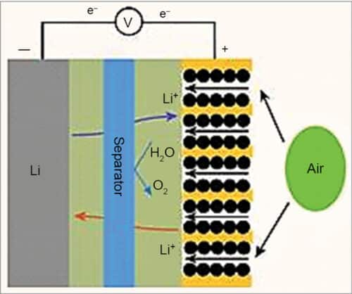
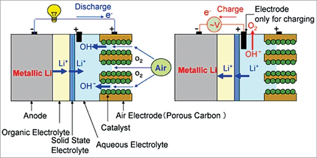
In general, lithium ions move between the anode and the cathode across the electrolyte. Under discharge, electrons follow the external circuit and do electrical work and lithium ions migrate to the cathode. During charging the lithium metal is electroplated onto the anode, freeing oxygen at the cathode (see Fig. 3).
Reaction during discharging is as follows:
Anode reaction: Li=Li-ion (Li+) +electron (e–)
Cathode reaction: O2+Li++e–= LiO2
2LiO2=Li2O2+O2
LiO2+Li++e–=Li2O2 (Eo=3.1V)
where Eo is standard cell potential.
Reaction during charging is as follows:
Anode reaction: Li-ion+electron =Li metal (plates onto anode)
Cathode reaction: Li2O2=Li-ion +O2+electron (freeing O2 at the cathode)
Depending on the type of electrolyte used, lithium-air batteries can be grouped into four categories (see Fig. 4):
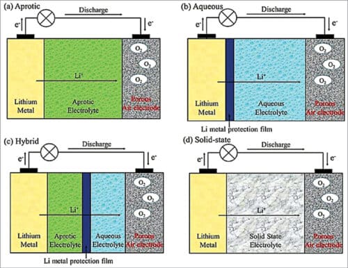
(a) Aprotic (using non-aqueous electrolyte)
(b) Aqueous
(c) Hybrid: (a)+(b) or (a)+(d)
(d) Solid-state
Aprotic electrolyte (non-aqueous) battery
As shown in Fig. 5, a typical aprotic lithium-air battery contains a metal lithium anode, an electrolyte comprising a dissolved lithium salt in an aprotic solvent, a conducting porous carbon supported oxygen-breathing cathode, and often a lithium-ion conducting membrane separating the cathode and anode. The destabilisation of the lithium metal interface by crossover of water, oxygen, and carbon-dioxide can fatally degrade the cycle life of lithium-air battery. Hence, usually, polyurethane separators are used that can effectively suppress this crossover while allowing lithium ions to diffuse through selectively. The membrane separator is a key component in a liquid lithium-air battery for electrically separating the cathode and the anode, meanwhile ensuring ionic transport between them and also protect the lithium metal anode from redox mediators.
The major discharge product at the cathode is lithium-peroxide (Li2O2) with a small proportion of lithium-oxide (Li2O). Reaction product Li2O is not desirable, because it is not reversible, being not fully rechargeable back to lithium and oxygen. Therefore, Li2O2 is considered the ideal discharge product at the cathode.
Here lithium metal is the typical anode choice, which however risks dendritic lithium deposits triggering a short circuit. During operation, layers of lithium salts are deposited onto the anode. This barrier eventually inhibits the reaction kinetics between the anode and the electrolyte. Earlier the commonly used electrolyte was lithium salt dissolved in ethylene-carbonate plus propylene-carbonate solvents but, unfortunately, they are also inflammable. However, such solvents are not stable to the superoxide radicals and could be decomposed during charge and discharge process, leading to fast termination of the battery.
Currently, the most common solvents used are ethers and sulphonate based solvents, which have long-term stability. Lithium salts like LiBF4, LiBOB (lithium bis borate), and LiTFSI (a hydrophilic salt), which have excellent stability and high ionic conductivity, are dissolved in these solvents to make the electrolyte. Lithium-air batteries with 610 cycles in ambient air have been made by combination of low-density polythelene film that prevents water erosion and gel electrolyte that contains redox mediator.
Gel polymer electrolyte (GPE) consists of polymer matrix like polythelene oxide or its derivatives, lithium salts, and plasticisers. It combines the advantages of both solid and liquid components. GPEs possess outstanding ionic conductivity, which can boost the electrochemical performance and have good interfacial properties from the liquid phase as well as good mechanical properties from solid component.
As the liquid electrolyte is immobilised in the pores of polythene matrix the risk of leakage of the liquid is reduced manyfold compared to commercial separators. It prevents the detrimental side reaction of discharged Li2O2 to Li2CO3 in ambient air, thus facilitating electrochemical decomposition of Li2O2 during charging, which improves the reversibility of the battery.
Another method uses lithium anode with a passivation layer of Li2CO3/C coating by treating with pure carbon-dioxide, which prevents the degradations of lithium metal from side reactions. This method achieves excellent cycling performance over 700 cycles, equivalent to several years of use. A new philosophy has now been developed that uses lithium as a soluble catalyst and the resulting battery can run stably for more than 900 cycles.
Cathode materials should have a durable porous structure, enabling it to store discharge products and provide channels for oxygen diffusion. They should have high electrolyte wettability for ionic transfer during charging and discharging. Cathodes should have the ability to accelerate the kinetics of oxygen reduction/evolution reaction (ORR/OER). In non-aqueous lithium-air batteries carbon materials are generally used to fabricate a porous cathode and they also can work as catalyst towards ORR/OER.
Carbon material with surface areas and larger number of mesopores could deliver higher discharge capacities. Functional carbon materials that are used as cathode substrate are generally graphene, carbon nanotubes (CNT), mesoporous carbon with pores having diameter between 2 and 50nm mixed with cobalt and manganese as catalyst, which enhances reaction kinetics and increases cathode’s specific capacity. They are quite effective exhibiting discharge capacities ranging from 7000 to 8700mAh per gm C.
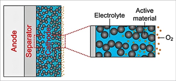
In conventional aprotic lithium-air batteries, the porous carbon composite air electrode (cathode) is fully saturated with the electrolyte, as shown in Fig. 6, which retards the transport rate of oxygen in the electrolyte to the reaction sites and the oxygen concentration at reaction site is very much decreased. Oxygen is first dissolved into the electrolyte at the oxygen/electrolyte interface and is then transported to the reaction sites. The insufficient supply of oxygen near the separator side limits the chemical reaction, leading to a lower power density output.
A possible remedy is to replace the fully saturated cathode into a partially saturated one by special chemical treatment, as shown in Fig. 7. In this concept, distribution of electrolyte inside the cathode pores due to partial saturation enables creation of uniform concentration distribution of both oxygen and lithium ions on the entire cathode surface. Gaseous oxygen can rapidly penetrate the pores and can be quickly transported to the reaction sites, leading to improved battery performance.

The separator in a lithium-air battery system is typically a porous polymer membrane that is wetted by the liquid electrolyte and located between cathode and anode, as shown in Fig. 8. The membrane separator is a key component in a liquid electrolyte battery for electrically separating the cathode and anode, meanwhile ensuring ionic transport between them.
In lithium-air batteries, the migration of moisture and oxygen from the air cathode to the lithium anode leads to unstable cycling. Therefore, ion-selective separators are required. The membrane materials are Nafion, LISICON, polymer of intrinsic microporosity, polyurethane, graphene oxide, polyethelene separator treated with polydopamine, etc. They allow the electrochemical reactions at both lithium metal anode and the air cathode to take place due to high lithium-ion conductivity. Further, they protect the anode from corrosion as moisture and oxygen are unable to penetrate through the separator membrane.
Lithium dendrite formation on lithium metal anode during charging/discharging in lithium-air batteries is a one way process and is quite harmful, causing performance decay. The above separators suppress lithium dendrite formation and show improved thermal stability against dimensional shrinkage at elevated temperature.
Aqueous electrolyte battery
An aqueous lithium-air battery consists of a lithium metal anode, an aqueous electrolyte, and a porous carbon cathode impregnated with silver. The aqueous electrolyte combines lithium salts dissolved in water. Here the problem of cathode clogging is solved because the reaction products are water-soluble.
This design has a higher practical discharge potential of 3.84V than aprotic type, which has cell voltage of about 2.92V. The energy density of aqueous system is about 30% lower than that of nonaqueous system. As lithium metal reacts violently with water, it is necessary to have water-stable lithium electrodes (WSLE) to obtain a practical aqueous lithium-air secondary battery that can survive lithium stripping for a long life span.
As shown in Fig. 9, this electrode consists of a composite lithium anode with a three-layer construction. This electrode concept adopts a water-stable sodium (Na) superionic conductor (NASICON) type lithium-conducting solid glass ceramic as a protective layer that covers and isolates lithium metal from direct contact with aqueous electrolyte.
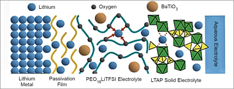
The glass ceramic is a compound of lithium (Li), titanium (Ti), aluminium (Al), and silicon (Si)—known as LTAP. But the LTAP is unstable in direct contact with lithium metal. So, a buffer layer of an electrolyte consisting of polyethelene oxide (PEO) and lithium salt is used between the lithium metal and LTAP plate. The bulk conductivity of PEO is increased by addition of nanosized ceramic fillers like BaTiO3.
The PEO electrolyte mixed with organic ionic liquid and nano silicon dioxide (SiO2) particles used in the buffer layer exhibits excellent effects for the suppression of formation of lithium dendrite. Aqueous lithium-air battery of this design has a life of more than 100 cycles. For application in electric vehicles, an effective design of the battery system should discharge during acceleration or cruise and be charged by regenerative braking.
Solid-state electrolyte lithium-air battery
Amongst all types of lithium-air batteries, non-aqueous lithium-air batteries possess a relatively simple structure and have many advantages. However, despite the advantages, they exhibit ignitability, toxicity, liquid leakage, and volatilisation because of their organic liquid electrolyte components. Moreover, lithium dendrites form during cycling, resulting in internal short circuit that leads to combustion and even cell explosion.
More seriously, the charging process is accompanied by the decomposition of organic electrolytes, leading to the accumulation of side products, gradually increasing overpotential and finally death of the cell. When operated in ambient air, corrosion of lithium metal occurs because water and other gases pass through the open structure of the air electrode and organic electrolyte.
These problems result in poor cycle and rate performance. One of the optimal methods to offset these disadvantages is developing solid-state lithium-air batteries, replacing the organic electrolytes with solid electrolytes, such as inorganic or polymer electrolytes. Fig. 10, shows a typical schematic arrangement of solid-state electrolyte lithium-air battery consisting of a lithium metal anode, a solid-state electrolyte, and a porous carbon cathode with suitable ionic and electronic paths, which have the potential to eliminate the aforesaid problems.

There is another advantage that these batteries don’t require separator. They can work over wide operating temperatures. The main drawback of this system is low conductivity of the ceramic electrolyte compared to aqueous and aprotic batteries.
Solid-state electrolyte is a solid ionic conductor capable of conducting ions in the solid state. It should have ionic conductivity, at least higher than 10–4 S cm–1, high ionic transference number (closest possible to 1), wide electrochemical stability window (ESW), at least 4 to 5V, and high mechanical strength of about tens of MPa.
Solid-state electrolytes can be divided into following categories:
1. Inorganic solid electrolyte (ISE) that is constituted by an inorganic material in the crystalline or glassy state, which conducts ions by diffusion through the lattice. These have high ionic conductivity at room temperature, high modulus of the order of GPa, and high transfer number. But they are generally brittle. They can be LISICON (lithium superionic conductor, for example, LGPS and LiSiPS) or NASICON (sodium superionic conductor like LAGP and LATP).
NASICON type solid electrolyte has a 3D structure with a tunnel for sodium ion transport. In the lithium ionic conductors, sodium ions are substituted with lithium ions in a similar structure. Among these compounds, Li1.3Al0.3Ti1.7(PO4)3 (LATP) ceramic reached a high ionic conductivity of 7×10⁻⁴ S cm–1 at RT. Another important NASICON type electrolyte is a compound of lithium germanium aluminium phosphate (LAGP) that demonstrates a conductivity of 2.4×10⁻⁴ S cm–1.
For the fabrication of cathodes (air electrodes), carbon materials like carbon fibre, carbon nanotubes (CNTs), graphene nanosheets, reduced graphene oxide, etc are widely employed. This is because they are cost-effective, possess a desirable electronic conductivity, have large surface area and catalyst activities. Moreover, they can be easily mass produced. Further, carbon is prone to form a favourable interface between carbon and solid electrolyte particles by mechanical milling or heat treatment.
The air electrode is made by mixing carbon nanotubes or other suitable carbon materials with ceramic electrolyte (LAGP/LATP) followed by heat treatment. RuO2 and NiO nanoparticles acting as catalyst are then added. The cells thus produced are able to sustain about 450 cycles (75 days) at ambient air.
Ceramic electrolytes like LAGP/LATP have been closer to commercial applications. However, several crucial issues still remain as obstacles to their practical application. Although the lithium-ion conductivity of the ceramic electrolyte is quite high and the interfacial impedance between the particles in the ceramic sheet can be minimised, the interface contact and interface compatibility of the ceramic and the electrode are challenging.
It is well known that achieving intimate solid-to-solid contact is extremely vital but also extremely difficult to achieve. Poor solid-to-solid contact commonly results in high interface resistance and the formation of lithium dendrites. In addition, it is very difficult for ceramic sheets to be defect-free, which also results in dendrite formation. Therefore, resolving interface issues is critical for the performance of ceramic electrolyte.
For better physical contact, introducing an alloy layer between the electrolyte and lithium metal or depositing the electrolyte material and the cathode material together are effective. The combination of ceramic electrolyte and polymer electrolyte is also a method to improve the interface engineering. Polymers are more liquid-like than ceramics and solid-liquid contact has inherent advantages over solid-solid contact. However, as the ionic conductivity of polymer electrolyte is lower than ceramic, it is important to find a balance point between the ratio of these two components.
Research work to address these critical issues is being carried out worldwide. It is expected that shortly solid-state lithium-air batteries would be commercially produced that could sustain cycling for at least more than 1000 times at ambient temperature suitable for electric vehicles.
2. Solid polymer electrolyte (SPE) that is defined as solvent-free salt solution in a polymer host material that conducts ions through polymer chains. SPEs are much easier to process and manufacture. They are elastic, giving stability at the interface, and are resistant to volume change during operation.
In general, their ionic conductivity is lower than of ISEs. Despite inferior ionic conductivity (<10–5 S cm–1) at RT, and poor electrochemical stability at high voltage, SPEs show high flexibility and low fabrication costs. Batteries with gel type polymer electrolyte made from a compound of polyvinylidene fluoride hexafluoroproylene have a moderate performance of about 180 cycles. A hybrid solid-state electrolyte using polymer and inorganic solid electrolytes is expected to give better performance.
3. Quasi solid-state electrolyte (QSSE) is a composite compound consisting of a liquid electrolyte that acts as a route to conduction of ions and a solid matrix that gives mechanical strength. At present, ceramics, LAGP, and polyethelene oxide (PEO) polymer electrolytes are employed as solid-state electrolytes. In terms of chemical and electrochemical stability, LATP and LAGP may be the most promising electrolyte.
Hybrid electrolyte battery
In this design both aqueous and aprotic electrolytes are used to have the advantages of both aqueous and aprotic battery design, as shown in Fig. 11. A lithium conducting membrane made of ceramic, glass, or polymer separates the two types of electrolytes in the cell.
The lithium anode is coated with lithium-conducting ceramic to protect the lithium metal from violent reaction with water. Li+ ion transfer between the liquid and solid phase is kinetically sluggish and consequently Li+ ions mainly migrate through the maze of the liquid electrolyte due to its higher conductivity.
It is important to mention that often the liquid components compromise the thermal stability and the safety of the battery causing explosion. They have a moderate performance of around 100 cycles. Hence, they are not suitable for electric vehicles.
Architecture of carbon cathode
In the near future it will be possible to manufacture commercial lithium-air batteries with practical specific energy ranging from 500 to 900Wh kg–1, which is at least two to three times compared to those of alternative rechargeable batteries, and therefore would be sufficient to deliver a driving range of about 600km in one charge.
The limited performance of lithium-air batteries is the result of several technical barriers, in particular the architecture of the carbon cathode material and the catalyst. An ideal cathode should have a porous structure, where microporous channels can facilitate rapid oxygen diffusion, interconnected pore channels can act as reactive sites between lithium ions and oxygen, and mesopores might serve as the accommodation sites for discharge products. Carbon in the following forms is best suited for this purpose (see Table 2).
| Table 2 | |||
| Architecture of carbon cathode | |||
| Surface Area (m2 gm–1) | Pore Dia (nm) | Specific Capa-city (mAh–1) | |
| Super-P | 62 | 50 | 1736 |
| Carbon nano balls | 314 | 14.3 | 3490 |
| Mesoporous graphene | – | up to 100 | 15,000 |
| CNT (carbon nanotube) | – | 15 to 30 | 2540 |
Due to its very high specific capacity, mesoporous graphene has received worldwide attention as a future cathode material.
The discharge and charging potential of lithium-air batteries are 2.7V and about 4.0V, respectively. Unfortunately, carbon materials are unstable above 3.5V in presence of Li2O2, forming Li2CO3, and severely reduce discharge-charge cycles. So, another main challenge is to design and use proper bifunctional catalysts that might give better ORR and OER activities to improve the cycle’s performance. The design of the catalysts is yet to be perfected.
Overview
Presently a number of aprotic electrolyte solvents, namely, sulfonamide based electrolyte, ionic liquid, ethers, propylene carbonate/lithium bis-trifluoromethansulfonilimide, sulphones, etc have been recommended. However, electrolyte degradation during the lithium-air battery cycling process hampers their commercialisation. Moreover, some of the electrolytes, being inflammable, pose a safety hazard. Thus, developing a stable and safe electrolyte is the key to the improvement of aprotic batteries.
One of the major advantages of the aqueous lithium-air batteries is that the discharge reaction product is soluble in water, eliminating formation of electrically-resistive products that may passivate the air electrode. During discharge process, water-soluble LiOH is produced, but precipitates to form LiOH-H2O crystals above its solubility limit of 5,25M. These crystals fill up the pores in the fluffy carbon electrode and retard the kinetics of both ORR and OER. But crucially the LiOH crystals do not coat and block the vital carbon surface that is generating the supply of voltage.
One way to overcome this problem is to use lithium iodide as ‘facilitator’ and water as co-reactant that boosts the lithium-air battery’s capacity. It turns out that negatively charged iodide ions are converted into I3 (triiodide) ions that combine with LiOH crystals and dissolve, allowing complete recharge by clearing the pores. In fact, this mechanism is even more effective than the recharge of Li2O2 attached to the electrode surface, since the electrons need not travel through Li2O2 layer, and hence less energy would be required to recharge the battery, promising an energy efficiency of 90% for aqueous lithium-air batteries.
Another disadvantage of the aqueous system is that its specific energy density is reduced significantly due to inclusion of solid electrolyte separator, which has considerable weight and volume.
The solid-state liquid-air battery is attractive with respect to the safety issues and long-term stability. However, lithium-stable and lithium dendrite formation-free high lithium ion conducting solid electrolytes are yet to be developed. Therefore, a lithium-stable interlayer—such as a liquid or polymer electrolyte—between the lithium anode and the solid electrolyte is required. The architecture of air electrode is very crucial as the cell capacity is dependent on it. Several other challenges still exist, such as:
- Insufficient ionic conductivity of the solid electrolyte, which is much lower than of the organic liquid electrolyte. Conductivity can be enhanced by increasing the crystallinity and forming nanosized solid interface through the space charge layer effect.
- Poor interfacial compatibility between electrode and electrolyte. High solid-solid interfacial resistances are usually produced after the initial charging process arising from large volume changes of the electrodes during lithiation/DE lithiation. These interfacial resistances can be reduced by depositing ultrathin layer of Al2O3 on garnet electrolyte. Another route to reduce the impedance is to increase the operating temperature, enabling speeding up of motion of ions in the solid-state system.
- The sharp interphases may cause lamination or large strain during cycles. Rational design of functional grade in the electrode/electrolyte interface and optimisation of electrode materials are still lacking.
All these findings reveal a promising way forward for lithium-air technology, at a time when many other research groups have given up further research. As more researchers return to the subject following many recent breakthroughs, perhaps a commercial lithium-air battery will finally become a reality within two years.
Rathindra Nath Biswas is a chemical engineering graduate of 1964 batch from Jadavpur University, Calcutta. He was awarded a postgraduate certificate from Giprokoks, USSR for designing Benzol Plant. He retired from service as Head, MECON, Durgapur