


This is a DIY Arduino-based overcurrent relay project that emulates Inverse Definite Minimum Time (IDMT) protection using an Arduino Nano and ACS712 current sensor. Instead of traditional electromechanical or thermal relays, this design uses software-defined inverse-time characteristics to protect electrical loads (especially motors).
Overcurrent relays with inverse definite minimum time (IDMT) characteristics are widely used in power systems to protect electrical feeders and loads from overheating under abnormal operating conditions. In these relays, operating time decreases with increasing current magnitude, enabling a faster response to severe faults. The standard ANSI device number assigned to an inverse-time overcurrent relay is 51.
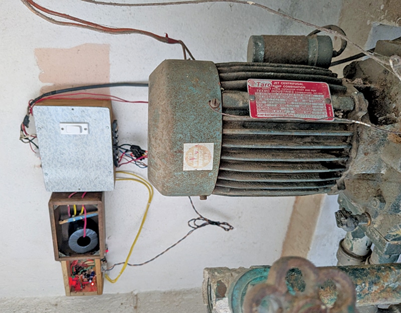
Although the proposed relay system is not thermal-based, it effectively emulates IDMT characteristics and is suitable for protecting induction motors, feeders, and other loads against prolonged overload conditions that could otherwise lead to winding failure or insulation damage. The implemented system, shown in Fig. 1, has been deployed on a domestic borewell motor to provide an alarm during overload conditions.

Also, check overvoltage and undervoltage protection for electrical appliances.
POC Video Tutorial
| Parts List |
| Semiconductors: Board1 – Arduino Nano board Sensor – ACS712-30A current sensor T1 – BC547 NPN transistor D1, D2 – 1N4007 rectifier diode LED1 – 5mm LED Resistors (all 1/4-watt, ±5% carbon): R1 – 1kΩ R2 – 10kΩ R3 – 4.7kΩ Miscellaneous: Jach1 – 12V DC socket S1 – Push-to-on switch CON1-CON4 – 2-pin connector RL1 – 12V, SPDT relay – 12V, 1A adaptor – Jumper wire as required – Wooden enclosure – AC load – Current transformer, CT (optional) |
EFY team verified and listed best electronic components online store in India. Check these websites before buying electronics components.
Overcurrent Relay Circuit
Fig. 2 shows the circuit diagram of the overcurrent/IDMT relay system. The system is built around an Arduino Nano, an ACS712 (30A) Hall-effect current sensor module, and a few supporting components. The load or feeder whose current is to be monitored is connected in series with the ACS712 sensor module.
Also check: Overcurrent Fault Detector.

