


Study of microprocessors is an integral part of the engineering programme, when we are taking up a course on electronics or any related discipline. And 8085 is probably the first microprocessor that we get in touch with as a part of the curriculum. Students are usually just given some basic hands-on training using standard boards with a keypad.
Whenever we are dealing with hardware, there is always a chance for it to fail. Moreover, there are some practical concerns while learning microprocessors using boards. If you would like to simultaneously determine the status of all the registers at a time, or analyse the working in varying speed of simulations, a trainer kit may have limitations.
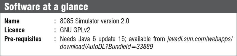
For electronics enthusiasts willing to learn programming of microprocessors, but limited by the availability of trainer kits, there are a handful of simulators available online as open source. In this article, let us have a look at one such 8085 simulator.
The 8085 programming model
8085 processor has a set of seven 8-bit registers including the accumulator and six others, namely, B, C, D, E, H and L. Depending upon applications, the registers other than the accumulator can be used either as independent byte-registers or as 16-bit register pairs.
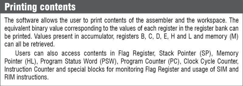
A 16-bit special-purpose register called program counter is available in the microprocessor. It stores the address of the next instruction to be fetched. A 16-bit stack pointer stores the address of the last byte entered into the stack.
Program Status Word comprising the accumulator and status registers is modified as per given instructions. An accumulator stores the result of an arithmetic and logical operation, and the result affects the content of various status registers.
What the simulator consists of
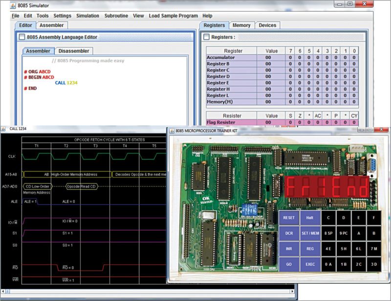
The simulator is designed to be very user-friendly and simulations are to be at par with actual hardware simulations. Let us have a quick look at the interesting features offered by the tool.
Assembler editor. This allows the user to input numerical data in binary, decimal and hexadecimal formats. The programmer can insert comments, label instructions and check errors using the editor. There are provisions for auto-correct, auto-intend and syntax highlighting. Moreover, users are allowed to run programs written in other simulators in this editor.
Disassembler editor. In most cases, the user is allowed to reverse-trace the original program successfully from the original code using this editor. The editor supports loading of hexadecimal file format that is specific to Intel.
Assembler workspace. The workspace contains Address field, Label, Mnemonics, Hex-code, Mnemonic size, M-cycles and T-states. While it supports the static-timing diagram for all instructions, dynamic-timing diagram for step-by-step simulations are also supported. It also provides error checking facility.
Memory and I/O editors. The memory editor allows users to choose memory range and to modify data in a particular memory location. Users can either view the entire memory content or the one in the loaded memory location. They can store data directly into a specified memory location.
The I/O editor required for peripheral interfacing enables users to edit the content directly.
Interrupt editor. An interrupt is a mechanism by which an instruction suspends normal execution of the program and gets itself serviced. A non-maskable interrupt cannot be ignored by standard interrupt-masking techniques in the system, while a maskable interrupt can be disabled by writing some instruction. The simulator supports a non-maskable interrupt in 8085 (TRAP), maskable vectored interrupts (RST 7.5, RST 6.5 and RST 5.5) and an externally-serviced interrupt (INTR).
The interrupt editor allows triggering of these interrupts by pressing appropriate columns in the interrupt table.
Debugger. The debugger allows users to have a step-by-step debugging of programs by traversing a program both forwards and backwards. They can put break points and continue the program from breakpoints.
Simulator. The simulator allows three levels of simulations. Users can have a step-by-step execution where they can halt between lines and simulate the code step by step. In the normal speed of execution, full execution takes place reflecting the intermittent states periodically. The ultimate execution reflects final state directly.
Supporting features
Crash recovery. Even if there is a sudden shutdown or crash of the application, the user can easily recover the program in this simulator.
Helper. Even if the user has very limited knowledge about user code, Code Wizard tool helps in programming 8085. The software is preloaded with a lot of sample programs to aid new users. The user manual further aids these.
Tools. The simulator has Insert DELAY Subroutine tool that allows users to generate a user-defined delay with the help of registers at a particular operating frequency.
Memory values can be set at corresponding vector interrupt addresses with the help of Interrupt Service Subroutine tool.
Number Conversion Tool facilitates inter-conversion between hexadecimal, decimal and binary number formats.
Enhanced laboratory experience
The software is designed mainly for users who do not have sufficient hardware to learn microprocessor programming. It uses the same simulation engine at the back end and the user gets the same lab experience while coding in the simulator. Moreover, there are a lot of inbuilt sample programs to aid self-learning. If you are new to microprocessor programming and really interested in coding, give it a try.
The author is assistant professor, department of ECE at SETCEM, Thrissur