


The system is designed to work like a roadside shopkeeper. When a customer places an order such as 1kg of apples, cameras connected to a GPU-enabled computer identify the required items and determine their location using computer vision.
The robotic arm, positioned at the centre of the shop for maximum reach, receives the target coordinates via Wi-Fi. It moves to the identified location, picks up the required quantity, and measures the weight using a load cell and distance sensor mounted on the gripper. It then places the items on a weighing tray. For an order such as 1kg of apples, the arm may make multiple pickup trips until the required weight is reached, after which the items can be packaged and delivered.
Object detection can be handled efficiently with modern AI models such as YOLO and specialised models like YOLOE for custom or uncommon objects. Since AI-based vision and path planning require significant computing power, they are handled by a GPU-enabled computer, laptop, or Raspberry Pi 5, while an ESP32 manages real-time hardware control.
Hybrid architecture
The system uses a hybrid architecture in which a GPU-enabled computer or Raspberry Pi 5 acts as the high-level processing unit. It performs computationally intensive tasks such as object detection, AI-based decision-making, and path planning. The resulting commands are transmitted to the ESP32 through Wi-Fi, Ethernet, or serial communication, depending on the application and system configuration.
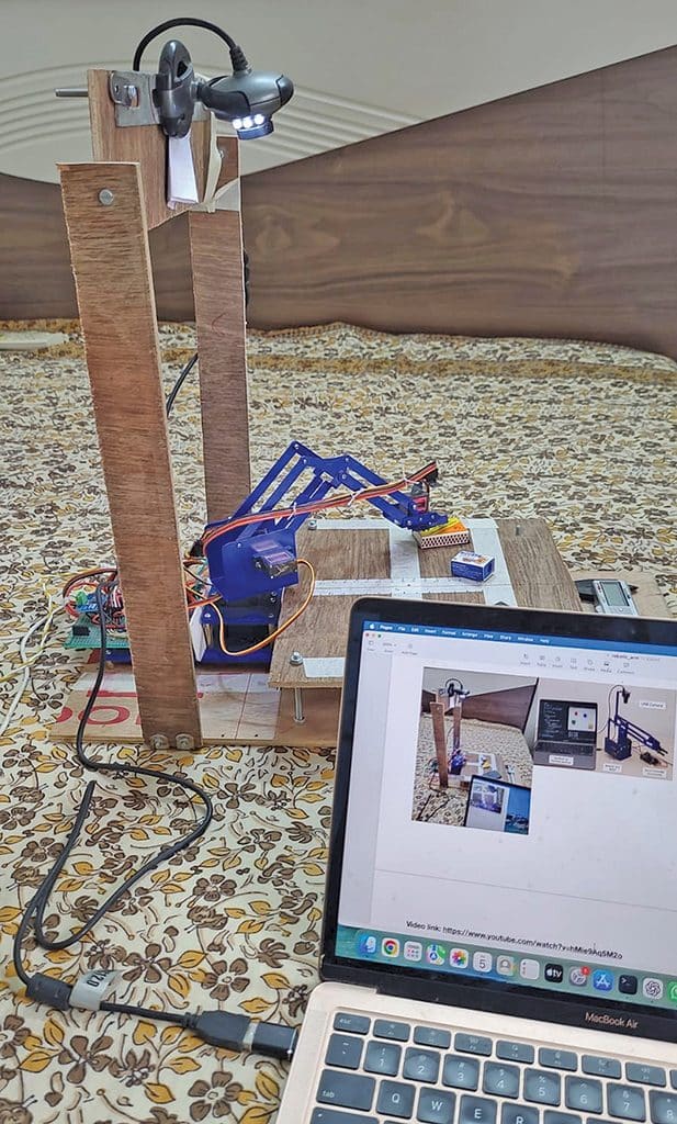
The ESP32 acts as the real-time control unit, interfacing directly with the motors, sensors, encoders, and gripper. It executes the commands received from the high-level computer and provides precise, responsive control of the robotic mechanism. The architecture therefore combines high-level AI processing with real-time hardware control. Fig. 1 shows the authors’ working prototype. The components required to build the system are listed in the Bill of Materials table.
| Bill of Materials | ||
| Component | Description | Quantity |
| ESP32 development board | Wi-Fi-enabled microcontroller for hardware control | 1 |
| PCA9685 PWM driver | 16-channel servo driver board | 1 |
| Hobby servo motors | Standard 180° pan-and-tilt servos (expandable) | 5 |
| VL53L0X ToF sensor | Time-of-flight distance sensor | 1 |
| 128×64 OLED display | SH1106 or SSD1306 I²C OLED module | 1 |
| USB webcam | External camera mounted on the pan-and-tilt assembly | 1 |
| INA219 current sensor | Current and voltage monitoring sensor | 1 |
| 100µF capacitor | Smoothing capacitor across the 5V rail | 1 |
| ATX power supply | Power supply unit with connector | 1 |
| Connecting wires | Assorted jumper wires and cables | As needed |
| Robot arm and claw kit | Mechanical arm and claw assembly | 1 |
Mechanical design and arm operations
The mechanical design of the robotic arm is critical to the system’s performance. It must provide adequate reach, payload capacity, positioning accuracy, stability, and workspace coverage while remaining cost- and energy-efficient. The design must also consider joint torque, arm geometry, cable management, and sensor placement for cameras, load cells, and distance sensors. Servos are suitable for smaller arms with limited rotational requirements, while stepper motors with encoders can be used where higher torque, greater angular range, and greater positioning accuracy are required.
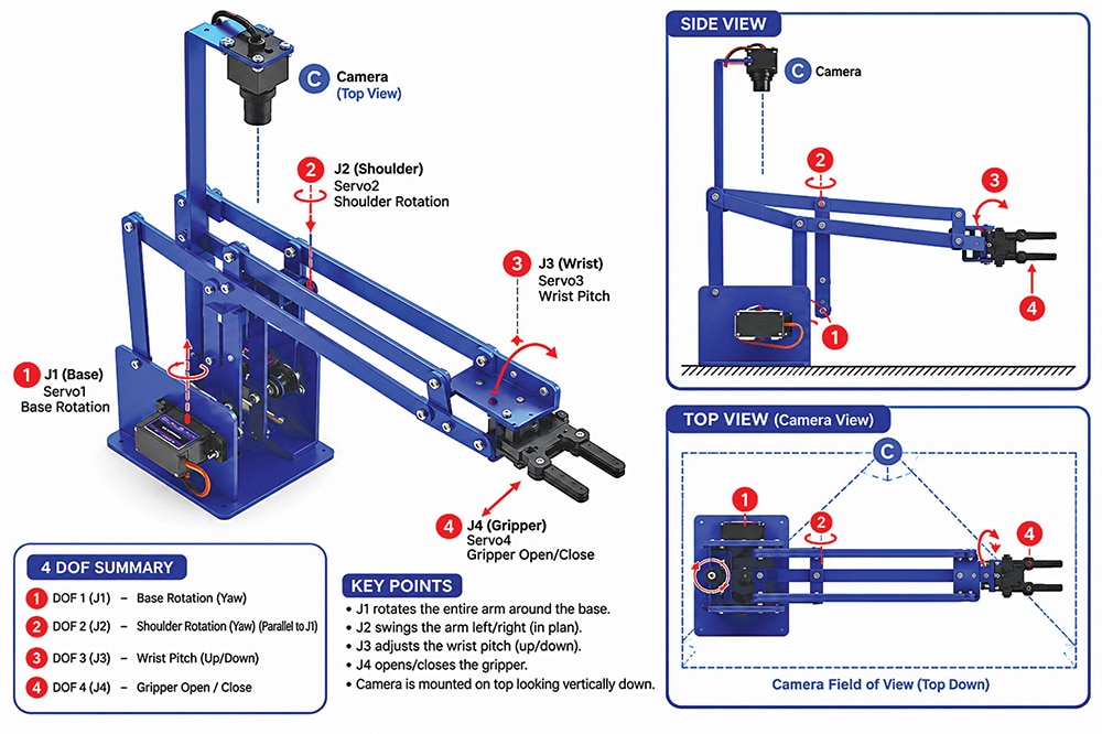
For objects placed on a flat surface, a basic arm can operate with approximately four DoF (degrees of freedom): base rotation, shoulder, elbow, and gripper. This is sufficient when objects are considered within a two-dimensional X-Y workspace. For true three-dimensional manipulation, additional DoF and depth perception are required. Stereo or depth cameras can provide the object’s Z-axis position, while additional joints allow the arm to orient and manoeuvre around obstacles.
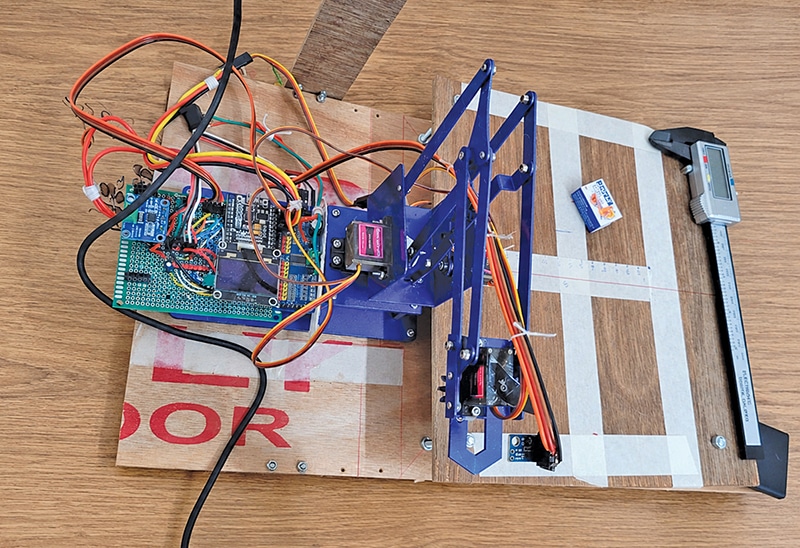
For fully flexible manipulation in 3D space, six DoF are generally required: X, Y, and Z positioning, along with roll, pitch, and yaw orientation. Most industrial robotic arms therefore use six or more DoF, allowing the end-effector to reach and orient objects in different poses within the robot’s workspace. Fig. 2 shows the completed arm setup, while Fig. 3 shows the arm assembly.
Circuit and control architecture
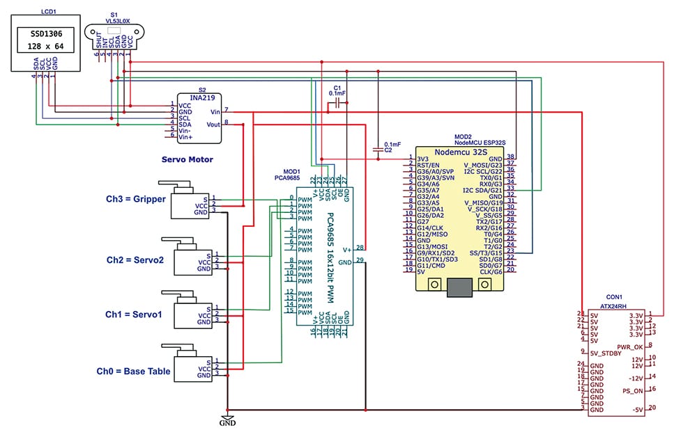
Fig. 4 shows the circuit diagram of the robotic arm. It is built around an ESP32-based NodeMCU-32S development board, which serves as the primary controller. An INA219 current/voltage sensor is interfaced via the I²C bus to monitor the electrical parameters of the servo monitor grips. Four servo motors are driven by a PCA9685 16-channel, 12-bit PWM driver, which provides multiple independent outputs for precise servo positioning. The PCA9685 communicates with the ESP32 via I²C, allowing the ESP32 to send PWM commands to control the angle of each servo. A 0.96-inch (2.4cm) SSD1306 128×64 OLED display is also connected to the ESP32 via I²C to show voltage, current, and other operating information. Capacitors C1 and C2 provide local supply decoupling to reduce noise and ensure stable operation. The system is powered through an ATX24R connector, which provides the necessary supply rails and a common ground. During operation, the ESP32 processes control commands, drives the PCA9685 to operate the four servo motors, and simultaneously receives voltage/current data from the INA219. The measured parameters are displayed on the OLED, providing real-time information about the servo system.
The robotic shopkeeper uses a hybrid control architecture in which a laptop, Raspberry Pi 5, or GPU server acts as the high-level processing unit, while the ESP32 handles real-time hardware control. The server performs object detection, AI-based decision-making, path planning, and high-level control, while the ESP32 handles real-time interfacing with motors, sensors, encoders, and the gripper. Communication between the server and the ESP32 is performed wirelessly through ESP-NOW, reducing cable clutter.