


Modern electronic systems use sensors to monitor parameters like temperature and provide protection from excessive temperature excursions with good accuracies, reasonable costs and often with low power consumption. For instance, expensive laptops with densely-packed circuits dissipate considerable power in the form of heat. Also, many compact and high-power portable equipment use cooling fans to keep junction temperatures at proper levels. These sensors provide temperature feedback to the system controller to make decisions such as over-temperature shutdown, turn on/turn off cooling fan, battery management, temperature compensation or general-purpose temperature monitoring system.
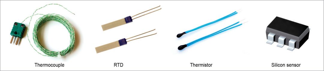
Most-common sensor technologies available to designers for measuring temperature within a system are thermistors, thermocouples, resistance temperature detectors (RTDs) and temperature-sensing ICs. Suitability of each technology for a system depends upon several factors such as: What device is to be measured? Is it ambient air temperature of an enclosure or an electronic component that may have high voltage present, or perhaps some part of an automobile engine? Important considerations driving the choice of sensors are temperature range to be sensed, overall cost, distance from sensor to instrument, cost of sensor, available area for the sensor to be mounted and so on.
Choosing the right sensor
Designing a temperature-sensing circuit involves many steps. One of the most crucial steps is to select an appropriate temperature transducer/sensor to match an application’s needs. Some key sensor characteristics to consider when selecting a sensor include temperature-measurement range, accuracy, response time, minimal temperature effect on the measured object and type of signal conditioning required. Other factors are long-term stability, mechanical ruggedness and cost. Some of these are discussed below.
Accuracy is needed in temperature sensing to enhance product reliability and performance. Assume that there is a system using a microcontroller (MCU) that operates up to 125°C before functioning abnormally. A better sensor with ±1°C accuracy will allow operation up to 123°C, whereas one with ±4°C accuracy will only allow operation up to 117°C. Many errors such as those introduced by the sensor, cabling or other hardware can affect the overall accuracy of measurement. Minimising these errors can lead to an increase in overall measurement accuracy.
Linearity is another important feature that affects accuracy in measurements. It defines the ability of a temperature sensor to give consistently-changing outputs over a range of temperatures. Linearisation techniques are often used to correct sensor non-linearity to achieve desired accuracy. All sensors require linearisation but to a different degree.
Signal conditioning is required with sensors as most of these provide low-level and non-linear outputs. To effectively and accurately measure signals, most analogue signals require some form of conditioning before these can be digitised and sent for further processing to the controller. For instance, filtering and amplification can dramatically improve the accuracy of thermocouple measurements. It is important that the required accuracy and resolution for an application is matched to the data acquisition and signal conditioning hardware that you select.
In the past, many complex analogue signal conditioning and calibration circuits were used that required manual calibration and precision resistors. Today, however, a digital design is used instead. Sensor outputs are often digitised by a high-resolution analogue-to-digital converter (ADC), which allows linearisation and calibration in software. This allows minimum operator involvement and also reduces cost and complexity.
Sensor excitation is another important concern. For instance, as RTDs and thermistors are resistive devices, you must supply these with an excitation current and then read the voltage across their terminals. If extra heat due to this cannot be dissipated, self-heating of the sensor is caused by the excitation current, which raises the temperature of the sensing element above the ambient temperature, thereby introducing errors in measurement. Power regulation is thus important to limit self-heating effects.
Stability defines how consistently a sensor maintains its accuracy over time. Generally, stability gets worsened by exposure to high temperatures. Wire-wound platinum and glass-encapsulated thermistors are the most stable, whereas thermocouples and silicon sensors are the least.
Temperature range varies for each sensor type irith the thermocouple family possessing the widest temperature range, spread across multiple thermocouple types.
Electrical noise can induce errors in temperature sensing. Mostly thermocouples and sometimes thermistors with very high resistances present this problem.
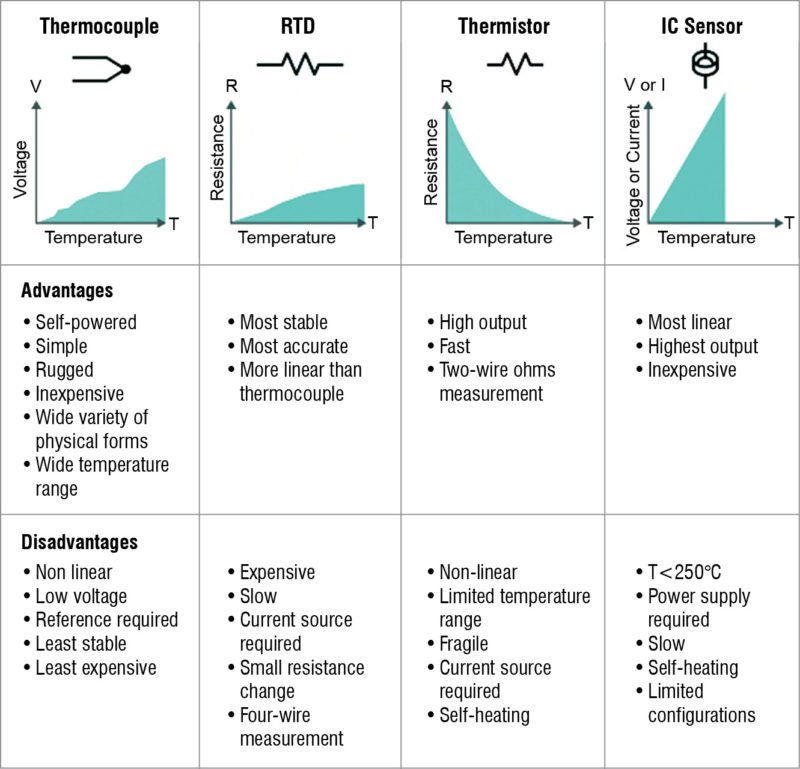
Sensor outputs vary by type of sensor. Most thermistors change resistance inversely-proportionally with temperature, thus the name negative temperature coefficient (NTC). Base metals such as platinum have positive temperature coefficient (PTC). Thermocouples have low milli-volt outputs that change with temperature. Silicon sensors are typically conditioned and come with a variety of digital outputs.
Cost is a major deciding factor. Although thermocouples are the least expensive and the most widely-used sensors, an NTC thermistor generally provides the greatest value for its price.
Sensitivity allows a sensor to sense very small changes in temperature.
Resolution dictates the smallest detectable change in temperature that a system can detect.
Flexibility allows a sensor to be configured into a wide variety of physical forms such as very small packages.
Response time determines how quickly a system can react to any change in temperature. Generally, the smaller the sensor, the faster the response time.
Thermocouples
Thermocouples are by far the most widely-used type of temperature sensors in the industry. Made by joining two wires of dissimilar metals, a thermocouple takes advantage of the voltage induced at the point of contact between the wires when these are heated. This voltage is proportional to temperature. Characteristics include wide temperature range (up to +2300°C), low cost, very low output voltage (about 40µV per °C for K type), reasonable linearity and moderately-complex signal conditioning. Signal conditioning for thermocouples requires a look-up table or algorithm correction.
Thermocouples are typically selected because of their low cost, high temperature limits, wide temperature ranges and durable nature. Applications for thermocouples range from industrial such as power generation, pharmaceutical and biotech to scientific and OEM applications. These are also found in everyday appliances like stoves, furnaces and toasters.
Measuring temperature with a thermocouple can be challenging because output signals are typically in milli-volt range, and generally thermocouples have very low temperature-to-voltage sensitivity. Therefore sources of errors related to thermocouple measurements that can impact measurement accuracy should be carefully considered. These are cold-junction compensation (CJC) errors, offset and gain errors, noise errors and thermocouple errors. Signal conditioning for a thermocouple involves CJC, amplification, isolation and filtering to remove these errors.
Let us walk through some important sources of errors and signal conditioning requirements in thermocouples:
Amplification. As output signals from thermocouples are typically in milli-volt range, these should be amplified. Gain is chosen according to the input limits of the ADC. Low-level voltages amplified near the signal source or measurement point typically improve the system’s noise performance.
CJC. It is important to consider CJC error, which is one of the largest contributors to the overall accuracy of measurements using a thermocouple. Connecting a thermocouple to a measurement device, in fact, creates three dissimilar metal junctions in a circuit: thermocouple junction (or hot junction) and junctions between each lead and measurement device (or cold junctions).
These cold junctions produce their own thermoelectric voltages proportional to the temperature at the device terminals. The technique used to remove this unwanted effect is called CJC, which uses another temperature sensor (usually a thermistor) to measure the cold-junction temperature, and uses this value to eliminate the parasitic thermocouple’s effects.
Noise errors. As thermocouple output signals are very low, typically between -10mV and 80mV, these are susceptible to noise introduced either by the external environment or by the measurement device. Thermocouple data acquisition (DAQ) systems generally use low-pass filters (LPFs) to eliminate high-frequency noise.
Common-mode noise and ground loops. Another source of noise arises when thermocouples are connected/soldered to a conductive material such as steel or submerged in conductive liquids such as water, which makes thermocouples susceptible to common-mode noise and ground loops. Isolation is required to prevent ground loops and improve the rejection of common-mode noise.
Thermocouple error. Another source of error is temperature gradients across the thermocouple wire due to impurities in the metals.
Thermistors
Thermistors are temperature-dependent resistors usually made from metal-oxide ceramics or polymers, whose resistance changes substantially with temperature, more so than standard resistors. Most of these are negative temperature coefficient (NTC) thermistors with their resistance dropping with temperature as opposed to standard resistors.
With a typical range of -100°C to +150°C, these are normally used for over-temperature shutdown purposes, monitoring the temperature of battery packs while charging, temperature of coolants and oil temperatures inside the engine to provide data to the engine control unit (ECU), and for temperature sensing in freezers and incubators.
Although thermistors are inexpensive and come in small packages, these are not as accurate as some of the other temperature-sensor solutions. These typically achieve greater precision within a limited temperature range. These are also non-linear, and their non-linearity can be addressed by software or by circuitry.
Of all thermistor disadvantages, self-heating is an important consideration. As discussed earlier, thermistors being resistive devices need an excitation current to read the voltage across their terminals, which results in self-heating. To minimise self-heat error to a low enough value, proper care must be taken to limit the sensing current.
RTDs
Platinum RTD is one of the most accurate sensors available for measuring temperatures within -200°C to +850°C range, capable of achieving calibrated accuracy of ±0.02°C or better. RTDs are resistive devices (often made from platinum wire) whose resistance varies with temperature. A 100-ohm platinum RTD, commonly called Pt100, has a typical resistance of 100 ohms at 0°C. Other characteristics include reasonable linearity and the need for signal conditioning. Cost of RTDs can be high, and these are available in probes, surface-mount packages and with bare leads.
RTDs are slowly replacing thermocouples in many industrial applications that work below 600°C due to their higher accuracy and repeatability. However, above these temperatures these are rarely used due to contamination of platinum at higher temperatures. Advantages of RTDs include high accuracy, low drift and suitability for precision applications.
Two common effects that can cause errors in measurements with RTDs are self-heating and lead-wire effects. These are explained below:
Self-heating. Passing current through an RTD generates a voltage across the RTD. By measuring this voltage, its resistance and, thus, its temperature can be determined. This causes self-heating of the RTD, leading to change in its resistance. This, in turn, results in error in the measurement. Self-heating effects can be minimised by supplying lower excitation current.
Lead-wire resistance. An RTD is often connected to a measurement device with a two-wire connection. These two wires that provide the RTD with its excitation current are also used to measure the voltage across the sensor. As RTDs have low nominal resistance, measurement accuracy can be greatly affected by lead-wire resistance. For example, one per cent measurement error can be caused by lead wires with a resistance of one ohm connected to a 100-ohm platinum RTD. To eliminate the effects of lead-wire resistance, a three-wire or four-wire connection method can be used, which creates high-impedance paths to effectively eliminate errors caused by lead-wire resistance.
Semiconductor temperature sensors
Semiconductor sensors are the easiest to measure temperature. These are designed to provide highly-accurate, repeatable results that require no compensation circuitry, lookup table or calibration. Modern silicon (IC) temperature sensors offer high accuracy and high linearity over an operating range of about -55°C to +150°C. The extremely low operating current minimises self-heating and maximises battery life. Often, these are integrated into multi-function ICs, which perform a number of other hardware monitoring functions. These are also useful in CJC circuits for wide-temperature-range thermocouples.
Semiconductor sensors can be local temperature sensors (analogue/digital) or remote temperature sensors. Local sensors are available with both analogue and digital outputs.
Analogue sensors. Until recently, all temperature sensors on the market provided analogue outputs. Unfortunately, these analogue outputs require a comparator, an ADC or an amplifier at their output to make these useful. Analogue temperature sensors develop an output voltage proportional to temperature with a nominal coefficient of 6.25mV/°C and 10mV/°C, respectively.
Device output is typically connected to a stand-alone or integrated ADC. These temperature-to-voltage converters can sense a -55°C to +150°C temperature range and feature an offset voltage that allows reading negative temperatures without requiring a negative supply voltage.
Applications include measurement of temperatures in instrumentation and consumer electronics, and LCD contrast control by measuring panel’s temperature in mobile phones.
Digital sensors. When higher levels of integration became feasible, temperature sensors with digital interfaces became available that communicate temperature data with the microprocessor through digital interfaces such as SPI, SMBus or I2C. Along the same bus, data is sent to the temperature sensor from the MCU, to set the temperature limit at which the alert pin should signal or interrupt the MCU when temperature limit has been exceeded.
If fan monitoring and/or control is included in this type of IC, the MCU is able to adjust fan speed or reduce the speed of a microprocessor, for example, to keep temperature under control. However, there are certain high-temperature scenerios when the MCU is not functioning. Then, another signal can be used to shut down the system power supplies directly, without the MCU, and prevent a potentially-catastrophic failure.
Digital temperature sensors often integrate a diode-sensing element, ADC, registers and communication interface. Available with ADC resolutions from 8 bits to 16 bits, 8-bit devices can provide around ±4°C accuracies, whereas 16-bit devices can give 0.33°C at room temperature.
Most digital temperature sensors include one or more outputs that indicate that the measured temperature has gone beyond a preset (usually software-programmable) limit. These typically function as a thermostat, notifying the system that a minimum or maximum temperature limit has been reached.
Often, these sensors are available in either hot (for temperature-increasing applications) or cold (for temperature-decreasing applications) option along with factory and user-programmable temperature settings. These are commonly used in fan controllers, power supplies, motor drives and RF power amplifiers.
Digital sensors offer many benefits over their analogue counterparts. Their more robust outputs than analogue sensors make these less susceptible to noise, allowing these to be placed 20 to 30 centimetres from the MCU even in noisy environments. Moreover, these can operate on the same bus used by other digital interface devices.
Analogue sensors need to be placed very closely to the MCU as the analogue output signal that carries the temperature information is susceptible to noise. For instance, some digital sensors can handle up to 300mV noise without delivering false data, whereas analogue sensors typically output 10mV/°C and start giving erroneous data if 10mV of noise is introduced.
Another advantage of using a digital temperature sensor is that all of the errors involved in digitising the temperature value are included within the sensor’s accuracy specifications. In contrast, an analogue temperature sensor’s specified error must be added to that of any ADC, amplifier, voltage reference or other component that is used with the sensor.
Remote temperature sensors. Digital temperature sensors can measure temperatures of remote diodes in addition to local temperatures in order to protect sensitive devices like field-programmable gate arrays, MCUs, video processors or power field-effect transistors. Remote diode-sensing chips are specifically designed to measure the temperature of a thermal diode or multiple locations on a PCB more accurately and convert it directly to digital form. Some of these ICs monitor a single thermal diode, while others monitor as many as four, using an SMBus interface.
Accurate fan speed monitoring and/or control is an important application of remote diode sensors, which improves performance of servers, video projectors and telecom equipment. Most fan controllers use pulse width modulation (PWM) to control DC fan speed rather than stopping operation when temperature rises. Some fans emit an audible sound at the frequency of the PWM signal controlling it.
Interestingly, remote sensors can implement very high free-programmable PWM switching frequencies up to 180kHz in steps to avoid audible noise of low frequencies.
Points to ponder
Given below are some important points to note while selecting a temperature sensor. Thermistors are the most sensitive but also the most non-linear. These are mostly popular in portable applications to measure battery temperature and other critical temperatures in a system. When a linear relationship between voltage and temperature is needed, a silicon temperature sensor is a far better choice than a thermistor. Over a narrow temperature range, however, thermistors can provide reasonable linearity and good sensitivity.
Many circuits originally constructed with thermistors have over time been updated using silicon temperature sensors. RTDs are accurate but require excitation current, and are generally used in bridge circuits. Thermocouples are rugged and can operate over the widest range of all temperature sensors. These are especially useful for measurements at extremely high temperatures in hostile environments.
Upasana Dewan is an electronics engineer having keen interest in writing about engineering design and innovation topics including the Internet of Things, artificial intelligence, robotics, optoelectronics and electric vehicles