


Multi-protocol label switching (MPLS) is a telecommunication transport mechanism that directs data from one network node to the next by using labels instead of long network Internet Protocol (IP) addresses, avoiding complex lookups in a routing table. So, what is MPLS all about? Let us find out.
In order to improve throughput and delay performance of IP, some sort of combination of standard routing protocols like open shortest path first (OSPF) and asynchronous transfer mode (ATM) switch networks were proposed in the mid-1990s. But these developments were not on a common platform. So, in 1997, Internet Engineering Task Force set up MPLS working group to develop a common standard that is free from any proprietary issues.
In 2001, MPLS working group issued its first proposal that clarified the kind of role MPLS could play in the world of the Internet. Before turning to the details of MPLS, let us briefly examine some basics.
Basically, switching is the process by which two circuits are interconnected for exchanging information and is basically classified as circuit switching and packet switching. Circuit switching is a connection-oriented routing technique that provides a permanent/dedicated path for the entire duration of a conversation.
Contrary to this, packet switching is a connection-less routing technique in which the entire message is divided into packets and then addressed and numbered. Packet switch sends the addressed and numbered packets one by one to the destination, in different routes, by using the entire available spectrum.
In this technique, no dedicated path is used between the source and destination. At the destination, packets arrive randomly at different times; the first packet may arrive last. The receiver has to wait until all packets are received. Finally, all packets are arranged sequentially and then converted into a message. Since the packets are routed through different routes, this routing becomes connection-less.
Although packet switching offers some advantages over circuit switching, it also imposes some limitations. Limitations of packet switching can be overcome by using label switching technique.
In label switching, connection-less IP routing is converted into connection-oriented routing by superimposing the network layer function with data link layer function. The label is attached to the data packet according to class and type of services in a similar way that is followed for categories and priorities in circuit switching. For further routing of the destined IP packet, intermediate routers use appropriate labels only.
Label switching is used in MPLS. The MPLS frame uses various data link frames like ATM, frame relay, point-to point IP/Ethernet (T1/E1) and synchronous optical network, among others. Since MPLS uses label switching and is a protocol-independent transport mechanism, it is called multi-protocol label switching.
MPLS architecture
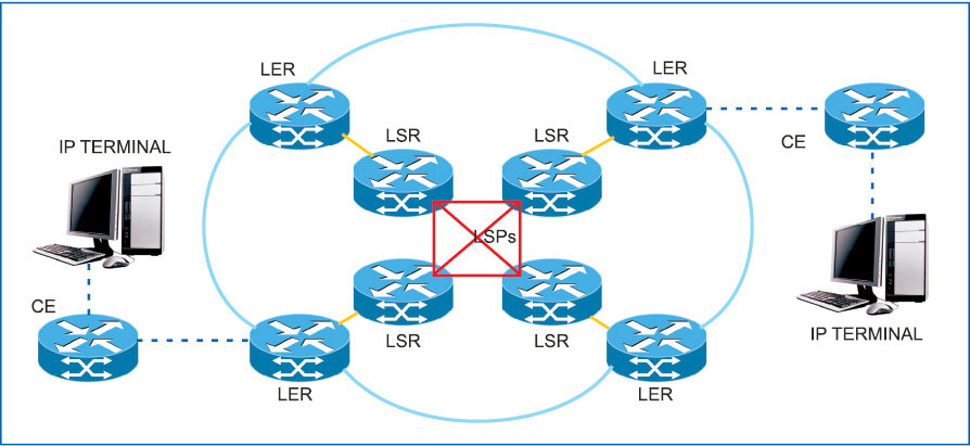
A typical MPLS architecture is shown in Fig. 1. Components of an MPLS IP network are customer edge (CE), label edge router (LER) and label switching router (LSR).
CE works at IP level. LER is the entry point of MPLS domain and is known as the provider edge. LSR works as a transit switch between LERs. Label switched path (LSP) is the data path between two routers through which packets travel. Lines shown between CE and LER carry IP packets bi-directionally.
Customer edge (CE). It structures the customer message into IP packets and sends it to the entry node of MPLS domain. While receiving IP packets from the egress node of MPLS domain, CE sends packets to the network layer of its own, after removing the IP address.
Label edge router (LER). This works as the gateway of MPLS domain and sits at the edge of the MPLS domain. Ingress LER receives IP packet from CE and assigns the appropriate label. After wrapping the label, it sends the labelled packet towards the next hop through LSP, which is assigned for the specific forward equivalence class (FEC). Assigning the label is termed as label binding. LER also acts as the egress router. Egress LER receives labelled IP packets from the previous transit router, pops up the label (removes the label) and routes the IP packets towards the destined CE.
Label switching router (LSR). This functions as a transit switch in MPLS cloud. It receives labelled IP packets through the appropriate LSP. It analyses the label bound over the packet, consults the forwarding information table [label information base (LIB)] and routes the packet through the appropriate LSP.
LIB is a software database created in both LER and LSR. It contains mapping information of the incoming label and LSP with outgoing label. It is created during installation of the router and, subsequently, updated automatically when the new LSR and LER are added by using label distribution protocol.
When LSR is routing the packets from the incoming LSP to the outgoing LSP, it strips out the incoming label and assigns a new label to the same packet to ensure security from intruders. This process is known as label swapping or label changing.
Label switched path (LSP). Within an MPLS domain, a path is set up prior to data transmission for a given packet to travel based on forward-equivalence class (FEC). There are two types of LSPs; one is static and the other is signalled. Static LSPs are configured manually on each LSR. No signalling protocol is used in static LSP. To establish a static LSP, the operator configures ingress LER, transit LSRs and egress LER, manually specifying labels to be applied at each hop.
Contrary to this, signalled LSPs are configured only at ingress LER. When a packet is assigned to a signalled LSP, it follows a pre-established path from LSP’s ingress LER to its egress LER.
How MPLS works
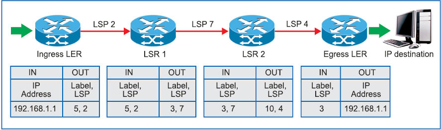
Suppose an IPv4 packet arrives at the ingress router (LER) from CE with a destination address of 192.168.1.1 (Fig. 2). In MPLS domain, ingress router has a route for 192.168.1.0/20 with a next-hop of LSP. A header with a label of, say, 5, selected from its LIB, is appended to the packet and forwarded downstream. LER binds the selected label (5) according to the FEC over the IP packet and sends it through the pre-programmed LSP (2) towards LSR1.
On receipt of the labelled IP packet, LSR1 analyses the label only and ignores the IP address. It consults with its LIB for further routing. As a result, it removes the incoming label (5), winds the newly-assigned label (3) over the IP packet and sends it towards LSR2 over the assigned LSP (7).
LSR2 consults with its LIB and transmits the IP packet after swapping the incoming label (3) with the outgoing label (10) towards egress LER over the pre-assigned LSP (4). Egress LER stripes the label (10), goes through the destined IP address (192.168.1.1) and hands it over to the correct CE.
Forward-equivalence class
FEC is a representation of a group of packets that share the same requirements for their transport. All packets in such a group are provided with the same treatment en route to the destination. FEC assignment is based on:
1. Class of service requirement
2. Quality of service requirement
3. Prefixes of IP addresses
FEC based on class of service requirement. IP packets from different users are categorised on the basis of class of services these are entitled to, and these are allotted with one FEC number. For example, one FEC represents all Voice over Internet Protocol (VoIP) packets received from different users, and in MPLS domain all VoIP packets are treated equally.
FEC based on quality of service requirement. Some online services like video conferencing require constant and high-speed data transmission. If delay exceeds, there could be a loss of intelligence. Such IP packets could not be made to wait in queue. Such services deserve separate FECs.
FEC based on prefixes of IP addresses. FEC is assigned on the basis of prefixes of the IP addresses of the destination.
MPLS label
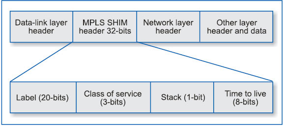
A label in MPLS is used as the routing code like an STD code in circuit switching. It identifies the path a packet should traverse in MPLS domain. The label is encapsulated in a data-link layer 2 header. So, a new layer called MPLS SHIM layer is formed between the network layer and data-link layer in OSI layer concept.
MPLS header has this name because an additional header is placed, or shimmed, between the existing data-link layer and network layers. Function of this layer is to bind MPLS label over the IP packet received from CE. The label contains information about the next hop address. Value of the label has local significance only. So, the same label number could be reused in some other area of MPLS domain.
Generic MPLS label format
MPLS layer works between the network layer and data-link layer (Fig. 3). MPLS SHIM layer is created in between L3 header and L2 header in all LERs for insertion of the label to IP packets received from CE. The first element of MPLS SHIM is a label field of 20-bit length that represents the label used to switch a packet. Label 0 through 15 are reserved by IETF (label 0 – IPv4 explicit null, label 1 – router alert, label 2 – IPv6 explicit null and label 3 – IPv4 implicit null).
All other labels may be allocated at random. Label binding and popping is done by ingress and egress LERs, respectively, while LSR does label swapping. MPLS label can be reused simultaneously within MPLS network, because the label has only local significance between the two LSRs.
Second portion of MPLS header is reserved for class of service (3 bits) and is used for the purposes of classifying LSPs based on differentiated services, and is also referred to as experimental portion.
The third portion (stack – 1-bit) is used for indicating the bottom of the stack. This bit is set to 1 for the last entry in the stack and 0 for all other label stack entries.
The last element in the header is an 8-bit field called time-to-live.
Label binding
Once a packet has been identified as a new or existing FEC, a label value from the underlying data-link layer is assigned to the packet. MPLS supports ATM, frame relay, PPP IP/Ethernet (T1/E1) because these have common characteristics like connection-oriented protocols, association with frame-level functioning and transfer of IP packets between adjacent nodes only.
So data-link layers (such as frame relay or ATM), layer-2 identifiers, such as data-link connection identifiers (DLCIs) in the case of frame-relay networks, or virtual path identifiers (VPIs)/virtual channel identifiers (VCIs) in case of ATM networks, or MAC headers in the case of PPP/Ethernet, can be used directly as labels. Packets are then forwarded based on their label value.
Labels are bound to an FEC as a result of some event or policy that indicates a need for such binding. These events can either be data-driven bindings or control-driven bindings. The latter is preferable because of their advanced scaling properties that can be used in MPLS. Policy of label binding is based on destination unicast routing, traffic engineering, multicast and quality of service.
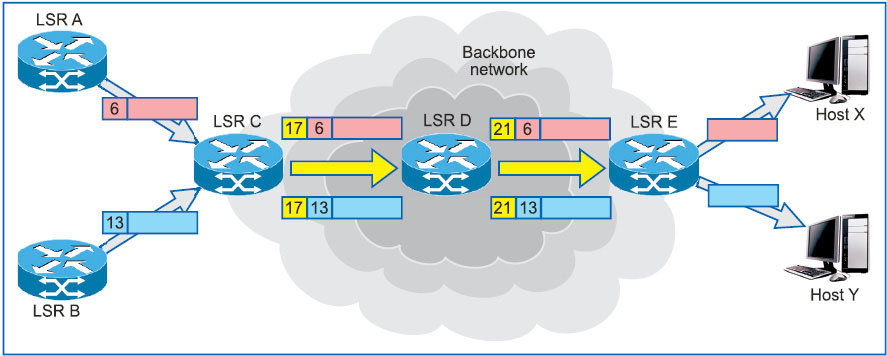
Label merging and stacking
Label merging is the replacement of multiple incoming labels for a particular FEC with a single outgoing label (Fig. 4). It is achieved by stacking the label at LSR based on the instant of arrival of packets through incoming LSPs. It is organised as a last-in, first-out stack.
Protocols used in MPLS network
An MPLS network uses different types of protocols like open short path first (OSPF), border gateway protocol (BGP), protocol-independent multicast (PIM) and resource reservation protocol (RRP/RSVP).
OSPF is a routing protocol that multicasts a change in the routing table of a host to all other hosts within the boundary of a network. In MPLS network, this protocol is used as a label-distribution protocol between peers. This protocol is one among interior gateway protocols (IGPs).
BGP is also a routing protocol that provides loop-free inter-domain routing between autonomous systems. An autonomous system is a set of routers that operate under the same administration. Here, an MPLS domain becomes an autonomous system. BGP is often run among VPN networks and MPLS networks.
PIM is used for multicast states label mapping. Some users may want to broadcast their messages to different users. This protocol supports the distribution of multicast labels. As a result, multiple LSPs are formed between single users to multi-users during broadcast period only.
RRP is not a routing protocol. It works in conjunction with other routing protocols to keep the quality of service within the MPLS cloud. It uses exchanging of labels pertaining to the services that require time management (online services like video conferencing, IP telephony and the like). RSVP provides the creation of tunnels in MPLS domain.
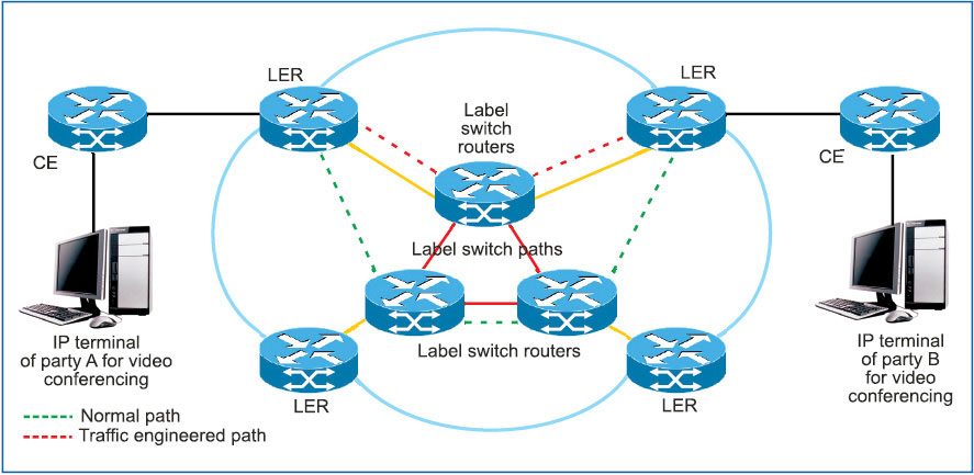
Traffic engineering in MPLS
Traffic engineering is essential for optimising utilisation of network resources. Network resources should not be wasted. At the same time, quality of service should be maintained for users.
In MPLS, layer 3 is overlaid with connection-oriented switching function of layer 2. By using this property, traffic-engineered dedicated paths for a different category of IP packets can be defined to maintain the quality of service. Thus, an MPLS network is converted into a homogeneous network to handle heterogeneous traffic. These dedicated paths are known as traffic engineered tunnels (Fig. 5).
Different types of traffic engineered tunnels are created based on the quality of service of different users. Thus, these tunnels provide an alternate path that has been deliberately configured to be used as an alternative, unused path through the network in an effort to utilise network resources in an efficient way.
Conclusion
In an MPLS domain, routers do not analyse the entire IP address to select the best matching but only analyse the label (similar to the analysis of route code in circuit switching), which greatly reduces delay in routing data packets. Thus, the amount of per-packet processing required at each router in an IP based network is greatly reduced with the use of MPLS.
Moreover, label switch paths and labels are selected for routing by label switch routers according to the FEC of that IP packet (category and priority). Since MPLS is a connection-oriented transmission protocol, chances of packet loss are rare. Security is ensured because of label swapping.
MPLS supports new capabilities efficiently and with full integrity, which has ensured its popularity in areas like virtual private network (VPN), Intranet, VoIP and video conferencing.
