Lithium iron phosphate (LiFePO4) cell is a type of lithium-ion cell that has higher storage capacity and can deliver higher power as compared to a lead-acid cell in a lead-acid battery. LiFePO4 batteries have long life due to their extremely robust crystal structures of the iron phosphates and have high voltage tolerances during charging and discharging.
A LiFePo4 cell may be safely overcharged up to 4.2V and normally does not catch fire like a Li-ion or LiPo cell. These cells are being used in most leading electric vehicles as cell packs due to their higher performance and increased lifespan.
LiFePO4 cell needs a constant-current and constant-voltage charging system, which can be fulfilled by the circuit presented here. This circuit can charge a single or two LiFePO4 cells in parallel. The circuit charges the cell in constant-current mode up to 3.4V and then it automatically changes to constant-voltage charging mode.
Circuit and working
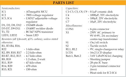
The circuit diagram of automatic LiFePO4 cell charger is shown in Fig. 1. It is built around ATmega8A (IC1), 5V voltage regulator 7805 (IC2), two LM317 adjustable voltage regulators (IC3 and IC4), a 16×2 LCD (LCD1), and two single-changeover relays (RL1 and RL2).
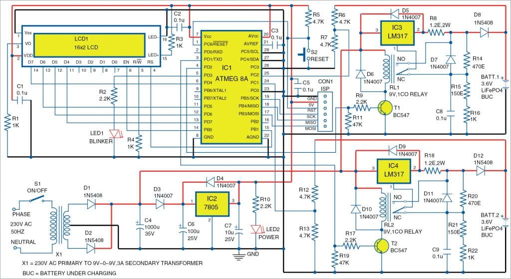
The charging system is controlled by ATmega8A microcontroller (MCU), which reads the charging voltage of the cell continuously and changes the charging mode to either constant-current (CC) or constant-voltage (CV) accordingly. The same is displayed on the 16-column by 2-row text LCD.
The main concept of the charging system is based on LM317 voltage regulator. The voltage regulator may be wired in either constant-current or constant-voltage mode with small changes in the circuit. The changes in connection are achieved by controlling the relay’s N/C and N/O contacts through the MCU. When the relay is on, the charger circuit is in CC mode, and 1A current is used for quick charging of the cell. Once the required cell voltage is achieved, the relay is switched off by the MCU and the charger circuit changes to CV mode.
The presence of the batteries, voltage of the batteries, status of the charging, mode of the charging (CC/CV), etc are all displayed on LCD1 for convenience.
Software
The program is developed in C language using AVR Studio4. It is compiled and the binary/hex code generated for the ATmega8A as LiFePO4_charger.hex.
Once the PCB is ready, the hex code is written/burnt to the MCU using a suitable AVR programmer and the MCU is placed on the PCB. You can also use ISP port to write the hex code directly using in-system programming. All the functions and variables used in the code are named properly to identify their purpose during programming.
Download Source Code
Construction and testing
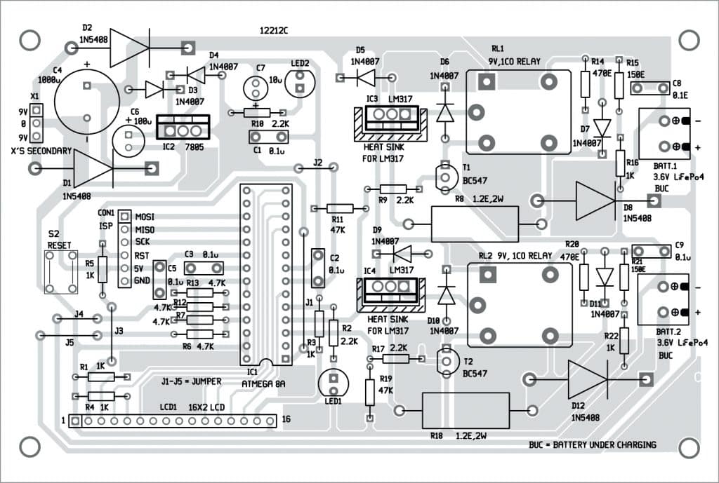
An actual-size PCB layout for the automatic LiFePO4 Cell charger is shown in Fig. 2 and its component layout in Fig. 3. After assembling the circuit on PCB, connect the 9V-0-9V secondary output of the transformer across X1 marked on the PCB. Also connect the primary of X1 to the AC mains via switch S1 (not shown in Fig. 3).
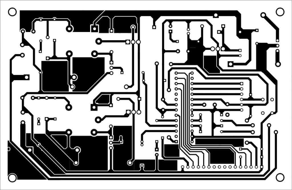
Download PCB and Component Layout PDFs: click here
On switching on the power supply through power switch (S1), blinker LED1 starts blinking and LCD1 displays a welcome message. Then the program starts the loop of reading the cell voltage and sets the charging mode to CC/CV accordingly. If the cell is charged fully, ‘Full’ message is displayed on LCD1. ‘Absent’ is displayed if the cell is not connected to the charging connector.
A good heat-sink should be provided separately for each LM317 to dissipate the heat generated in CC mode.
Fayaz Hassan is a manager at Visakhapatnam Steel Plant, Visakhapatnam, Andhra Pradesh. His interests include MCU projects, mechatronics and robotics