


Designers struggle to find the right mechanical and electronic design and simulation software. Innumerable meetings and brainstorming over alternatives eat into their time and energy. Worse, they end up buying the software, paying a hefty amount for it. Thankfully, a savior has emerged. FreeCAD is an open source mechanical CAD freeware that is as good as its paid counterparts. Its latest version, VER 0.16, is out in the market and ready to ease the work of designers.
A no-cost, easy-to-use tool
FreeCAD is a user-friendly tool with features of design, simulation and strength calculations for the product. Users need no prior training to be able to use it. After design, a mesh frame is created, which is followed by simulation (Fig. 1).

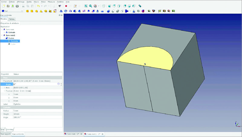
Consider the case when a designer is making metallic housing for an LED street-light. The designer needs to understand areas that would be under more mechanical stress or require more strength. He also needs to understand thermal management in the housing. Also, there will be calculations related to mechanical functions. The FreeCAD software comes handy here: It would first work on the design workbench, then mesh for strengthening the design, and finally simulation.
How FreeCAD helps
The latest version of FreeCAD, 0.16, has some additional features;
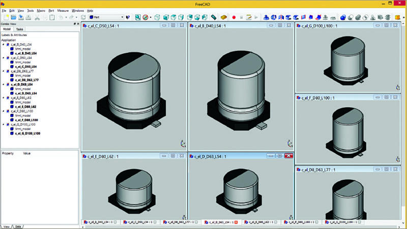
Expression Support.
FreeCAD helps make models using Excel spreadsheet format, just like in CATIA. Called Expression Support, this helps designers to get the precise location of coordinates. FreeCAD works on the concept of workbench.
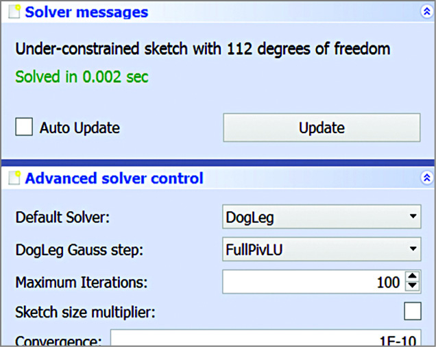
Sketcher Solver upgrade.
Sketcher Solver was introduced in the previous version (0.15), but in the new version (0.16) it makes sketch editing even faster and more stable than the previous version (Fig. 2).
Touchscreen 3D navigation.
This makes it easy to navigate. The designer can move the design in any direction with a single finger drag. So FreeCAD can be used without a mouse on a convertible laptop with touchscreen and pen, away from a desk.
New tools to reduce work stress.
Mechanical parts can have a regular or a discrete shape. Older versions of FreeCAD software did not take various shapes into consideration, making it a constraint for designers to work freely on any dimension.
New tools for connect, embed and cutout have been introduced in the latest version. Tools for shapes such as round, trunc, ceil and floor have also been included; version 0.15 featured shapes like parabola and hyperbola. Besides, new features have been introduced for toggle mode, continuous creation mode, speed up, duplication and mirroring (Fig. 3). Rectangles, wires and lines can now be subdivided, allowing all kinds of new shape combinations.
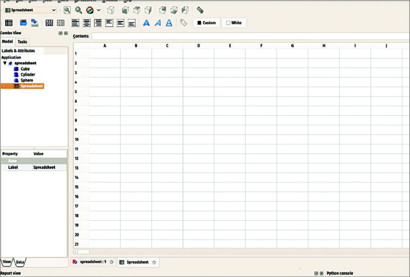
A new spreadsheet view tool allows users to place a range of cells from a spreadsheet on a Drawing page (Fig. 4).
Edit in real time.
You can see the 3D view in real time. This helps you visualise the actual dimension values of a shape. The new Finite Element Method (FEM) workbench allows cleanups, while Path workbench adds editing and import. So you can change the values in real time too. Edits made are saved immediately, helping you to conceptualise in a better way.
FEM workbench GUI
FreeCAD workbench consists of pre-processing, solving and post-processing.
Initially, geometry is modelled, then an FEM mesh created out of the geometry model. Load and support fixes are added to the model. Finally, the material is added.
The designer prepares a framework or skeleton of the design. Then he can use FEM to sort out problems like heat transfer, fluid flow or structural analysis. This is totally based on algebraic calculations.
Once the designer is sure of his designed product, he can give finishing touch to it. For example, in the case of a mechanical pulley system, once the freeware finds the design perfect as per calculations, the designer can define the places where the miscellaneous parts of pulley like nuts and bolts can be tightened.
Note
To read manual, please visit this page. For installation manual, refer readme files.
Feel interested? check out these articles.


Interestrd