


Jtagulator is a powerful tool used in electronics to debug and test hardware. It facilitates communication with embedded devices by identifying and mapping JTAG pins, enabling users to access the device’s firmware and perform various diagnostic tasks.
With its ability to identify JTAG pins accurately and efficiently, Jtagulator streamlines the hardware analysis and debugging process, making it an essential tool for electronics engineers and enthusiasts alike.


JTAG
JTAG, or Joint Test Action Group, is a standard protocol used for testing and debugging integrated circuits, particularly on printed circuit boards (PCBs). It consists of a set of pins that enable communication with embedded devices for various purposes, such as programming, debugging, and boundary scan testing. Also, we can modify firmware using Jtagulator.
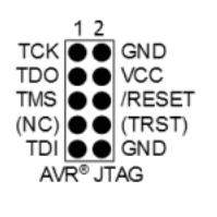
JTAG pins, typically labelled TDI (Test Data In), TDO (Test Data Out), TCK (Test Clock), and TMS (Test Mode Select), provide a standardized interface for accessing and controlling devices during development and production. JTAG’s versatility makes it invaluable for diagnosing hardware issues, verifying connections, and programming firmware in electronic systems.
Scenario
In the realm of PCBs, JTAG pins serve a pivotal purpose, allowing developers to program and extract code from the device. These pins, constituting TDI (Test Data In), TDO (Test Data Out), TCK (Test Clock), and TMS (Test Mode Select), are essential for device functionality. By understanding the configuration of these pins on the PCB, one can attempt to alter code and download firmware stored in the System-on-Chip (SOC).
Jtagulator emerges as a key player in this process. Through its IDCODE scan feature, Jtagulator seeks to identify three out of the four crucial pins (TDI, TDO, TCK, and TMS) within the JTAG port, facilitating further analysis and manipulation of device firmware.
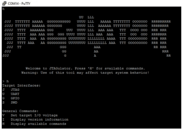
This is all the target interface in the Jtagulator
- J JTAG
- U UART
- G GPIO
- S SWD
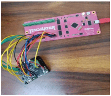
We’re currently in the process of pinpointing the JTAG pins within the target device. To achieve this, we’re establishing connections between the Jtagulator pins and the target device.
I’m about to initiate the IDCODE scan on the target device. To do so, I’ll select option J to enter the JTAG mode. Within the JTAG mode, various scan options are available, and I’ll specifically choose the IDCODE scan to identify the JTAG pins.
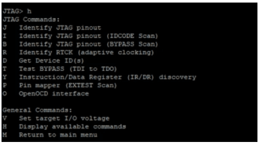
After running the IDCODE scan by selecting the “I” command in JTAG mode.
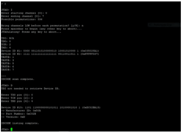
After running the IDCODE scan, Jtagulator successfully identified the TDO, TCK, and TMS pins from the target device. Therefore, the remaining pin should be TDI. With this information, we now have all four pins of the JTAG port on the target device, thanks to Jtagulator.
