In this article we take a look at eSim, a powerful open source software for integrated electronic design applications including circuit design, simulation, analysis and PCB design. The software is built with the help of popular open source software such as Ngspice, KiCad, Scilab and Python.
It is developed as an open source alternative to commercial software like OrCAD, Xpedition and HSPICE. Educational institutions and small and medium enterprises can effectively use this software that offers the user experience and capabilities equivalent to proprietary ones.

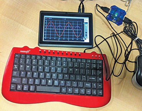
(Image courtesy: www.aakashlabs.org/gnu)
An all-in-one EDA package
There are a series of steps involved in electronic design automation (EDA). In the first step, specifications are laid down. These specifications take the shape of a design that could be in various forms such as a schematic circuit or a logical description in a High-level Description Language (HDL). The design is then simulated and redesigned, if necessary.
Once specifications are met, the design is converted into a PCB layout, a chip layout or ported to a field programmable gate array (FPGA). The product thus obtained is again checked to see if it meets the specifications and, for that, the entire cycle is repeated till desired results are obtained.
A large number of proprietary EDA tools including Cadence, Synopsys, Mentor Graphics and Xilinx can perform all these jobs in a comprehensive fashion. Unfortunately, the cost associated with the purchase of such proprietary design tools discourages the student community from colleges as well as SMEs from playing around with such tools.
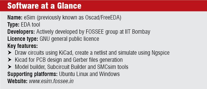
eSim, previously known as Oscad or FreeEDA, took its shape in IIT Bombay under free and open source software in science and engineering education (FOSSEE) group, making the software a viable alternative to open source ones.
Advanced features
Rakhi R. and Kannan M. Moudgalya in their article titled, ëOscad: Open Source Computer Aided Design Toolí discuss the advanced features of this tool. Let us take a quick glance at these.
Model Builder. How well the devices in the simulations are modelled is a prime determinant factor of the accuracy of the simulation. A set of device models including bipolar junction diodes, bipolar junction transistors (BJTs) and field effect transistors (FETs) are provided.
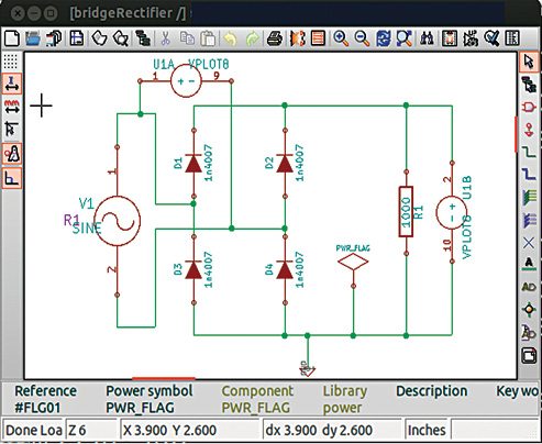
Suppose we are dealing with a bridge rectifier circuit. Parameters in the device model (say, the diode) can be set using the model builder tool and can even be reused by exporting the design into other files.
Subcircuit Builder. A complex circuit can be broken into simpler sub-circuits and could be reused in other projects. This ensures scalability and modularity of the design.
Scilab based Mini Circuit Simulator (SMCsim). Electronic simulations are based on mathematical equations. In order to impart a clear idea of how the entire simulation actually works, it is necessary that mathematical equations are provided along with simulations. This unique feature of eSim helps users get a clear picture of simulations.
The tool runs in three modes. It solves circuit equations and gives the final simulation result in normal mode. Users can also view symbolic equations along with the result in symbolic mode. Numerical mode gives intermediate numerical values of elements and components in system matrices along with symbolic equations and the final result.
The other modules
We have already described the key features of the software. Let us now have a quick look at other important modules used in eSim software.
 EEschema. This is an integrated software library where functionalities of circuit drawing, control, layout, library management and access to PCB design software are carried out. This schematic-capture software also provides the netlist describing the electrical connections of the circuit. eSim developers have extended its functionality by incorporating software libraries for voltage and current sources.
CvPcb. This is basically a footprint editor tool that helps users to associate schematic components to component footprints in the PCB design.
Pcbnew. Pcbnew is the layout editor tool from KiCad. CvPcb tool assigns components for the netlist produced by EEschema to the module used by Pcbnew.
KiCad to Ngspice netlist converter. This module is developed by eSim developers to facilitate easy conversion of KiCad-generated netlists to Ngspice-compatible formats.
Analysis Inserter. This module helps in inserting the type and options for various kinds of analyses of electronic circuits. Various types of analysis such as operating point analysis, AC and DC analysis and transient analysis can all be done with the help of this tool developed for eSim.
Ngspice. This is yet another general-purpose circuit-simulation program for non-linear DC, non-linear transient and linear AC analyses. Simulation can contain components including resistors, capacitors, inductors, transmission lines BJTs, FETs, metal oxide semiconductor field effect transistors, etc.
eSim workflow
The circuit diagram drawn on paper is entered into a computer using EEschema, which is the schematic editor used in this software. Apart from the library that provides voltage and current sources, there is yet another one created for printing and plotting purposes. The netlist file provided by this schematic editor contains electrical connections involved in the design.
Physical components are mapped into their footprints for creation of the PCB layout. CvPcb tool is used for this footprint mapping. The PCB layout is drawn with the help of Pcbnew. It is not always practical to check the accuracy of the design using breadboard testing. Model Builder helps in creating accurate models and editing existing models. Hierarchical modelling helps in designing complex models. Subcircuit Builder helps in creating sub-circuits.
Netlst converter helps in the conversion of netlists into a Ngspice-compatible format. Analysis Inserter proves to be an effective graphical interface for various types of simulations performed.
For analogue-, digital- and mixed-signal circuit simulation, eSim uses Ngspice software. SMCsim is also provided.
An indigenous open source software
There is a welcome trend in the country to promote the use of open source software, wherever possible. eSim was developed by the research group at IIT Bombay as a part of this initiative. The widespread use of open source software will certainly encourage a lot of people into serious research, especially in an economically-developing country like India where mastermind ideas are limited by shortage of funds.
The author is an electronics enthusiast from Kerala