Digital electronics rarely leaves you, no matter where you go. Right from the small register in your controller to the multiplexer that routes the signals in your circuit, it is present in almost everything you handle. The subject being a delight for some and a nightmare for the others, this article introduces a tool that helps make your digital logic design experience easy and pleasurable. Have a look at Logic Friday.
Visualise your digital logic function in totality
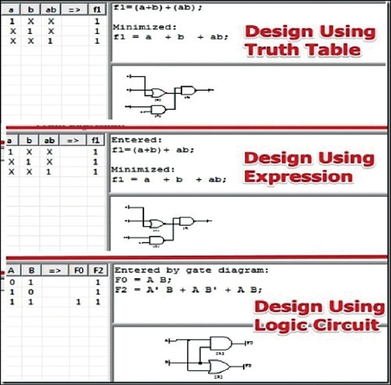
The logic of any combinatorial system design is always analysed for all possible input combinations, the different states its output can take, an expression for every possible output and, the most favourite of all, the logic diagram. Logic Friday lets you ease over the process by simultaneously viewing and accessing four windows: functions, truth table, equations and gate diagrams. When you make a modification in one window, the change is reflected in the others automatically. Every function includes a detailed description, right from the number of inputs and outputs to the number of min terms that make it true.

Espresso for efficient minimisation
Logic Friday takes the help of Espresso logic design minimiser to efficiently reduce the functions in your electronic design. Instead of using the traditional Karnaugh map method of min term reduction, the program manipulates the function iteratively to give a closely approximated result, eliminating redundancy. The same result is optimised by factorisation and mapped onto basic cells in the technology library, while dealing with field programmable gate arrays and application specific integrated circuits. This method of minimisation turns out to be efficient, using less memory and computation time.
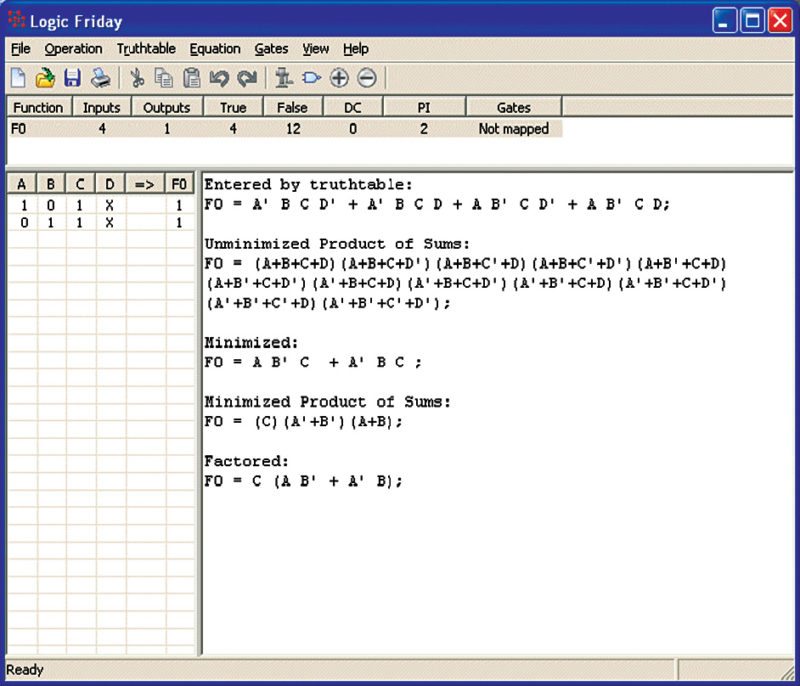
You have options of performing a fast or an exact minimisation. The former would give you a good result that may not be truly minimal, while the latter takes a significant amount of time to give you the perfect result.
Also, for functions with multiple outputs, you can choose to jointly optimise the total number of product terms or independently optimise each min term. The second is useful while mapping to gates, as you will end up with a simpler gate diagram, but might result in a large number of terms in the resulting function.
The function explained as gates
There is no digital electronics without a gate diagram. Universal gates NAND and NOR help represent any complex logic design, and one of the two will have to be specified as the type for mapping your design to gates.
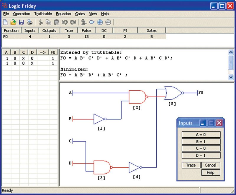
Logic Friday has support from MisII for gate diagram synthesis. You can optimise the diagram for standard integrated circuits (ICs) that will minimise the total number of IC packages in your design, or optimise for die area, letting the program choose gates to create a custom IC with minimum die area. Mapping to gates automatically minimises function.
The other important factor is tracing digital logic design in a gate diagram. Choosing this option automatically adds colour to the diagram, with a red for logic high and blue for logic low. You can thus view how your signal travels from input to any point in the circuit. To observe the result for other cases, change the input combination in the tool window and visualise the trace displayed.
Compare functions to find differences
Logic can get very confusing. Two gate diagrams may look very different but end up being copies of each other; an equation might seem perfect but miss a small bar or dot, and the changes certainly show. If you have two equations with the same number of inputs and a single output, Logic Friday lets you do a comparison between the two and find the differences between these.
Possible cases could be equal, unequal or one being a sub-set of the other. With various input combinations possible, the tool even tells you exactly for which rows the two functions happen to be alike.
Further, you even have a choice to clone a function to save a copy. Very useful when you have to move back a few paces while designing something complex.
Play around with your equations
Depending on need, convert your equation to look like you want it to. Be it a sum-of-products form or a product-of-sums form, factorise it or leave it expanded. The variable names and equation formats follow a given syntax of representation. The equation can be assigned values of true, false, don’t care or invert. If the input to an equation is a don’t care, the tool understands the input to have various values. It creates an exclusive table for it, while not considering it for minimisation. A don’t care in the output is important as it influences calculation of results.
A look-up table for implementing in software
This feature comes in very useful when you have a logic function that needs to be carried forward to software or firmware. Simply choose the ‘generate C look-up function’ tab under operations menu. Logic Friday then creates a stand-alone module that can be added to your source files. You need to specify the size of type ‘unsigned int’ on the processor or compiler for the software to properly distribute output truth values over bits of a data table. You can select how you want the function to be represented and called in C code. Every output will be assigned its own look-up table and don’t care conditions will be considered logic high.
Offering the much needed flexibility
Once done with experimentation and designing the digital logic circuit, Logic Friday save your digital logic design very easily. It simply exports the truth table into an Excel file with a .csv extension. It also saves the gate diagram into an image file in formats such as Windows bitmap (.bmp) or enhanced metafile (.emf).
For logic equation or gate diagram, print these to save a copy. For diagrams that may not be legible in a single page, a road atlas style is followed. It is used to print on two sheets, without losing continuity.
You can even choose to import a truth table before you begin working on your design (digital logic).
For more information: click here
Do you like this article? For more software reviews: click here
Priya Ravindran was working as a technical journalist at EFY until recently