


The need for a schematic editor arises from the complex electronic systems that were once manually drawn by engineers and designers. Today, most modern schematic software are equipped with state-of-the-art tools that can handle very complex circuit conception to its final product. This is how digital schematics were born.
XSCHEM could be that tool of choice that lets you work with nets, pins and wires. Knowing these basics marks the beginning of formal circuit design followed by simulation. During the first step in a design cycle, you have to make sure that the tools in the schematic editor are well understood. Once the schematic has been drawn on the computer, circuit connectivity and device netlist are generated and sent to a circuit simulator.

Judging a book by its cover
To make this process effective while transcending the concept from your mind to the editor, an easy graphical interface is required. By focusing on interfaces, hierarchy and instance properties, this software helps simplify a complex system and creates an illustration that looks like small building blocks of the project.
XSCHEM is made more attractive by its capability to handle integrated circuit (IC) design and to generate netlists for very-large-scale digital, analogue or mixed-mode simulations.
A netlist is generated with every simulation, and that provides a textual description of a circuit made of components. Components such as gates, resistors, capacitors and transistors can all be listed together to form a netlist when used in analogue simulation tools. Once the schematic is created, a circuit netlist can be generated for simulation.
Currently, XSCHEM supports three netlist formats:
• SPICE netlist
• VHDL netlist
• VERILOG netlist
Give the benefit of the doubt
XSCHEM could be looked upon as a featureful industrial-grade software. As you can see in Fig. 1, it is a depiction of VLSI system(s)-on-chip imported in XSCHEM. In the figure, the tool is seen handling more than ten hierarchies, and the primary goal of this program is to build a bigger schematic. This has been the primary goal during the whole development of the program.
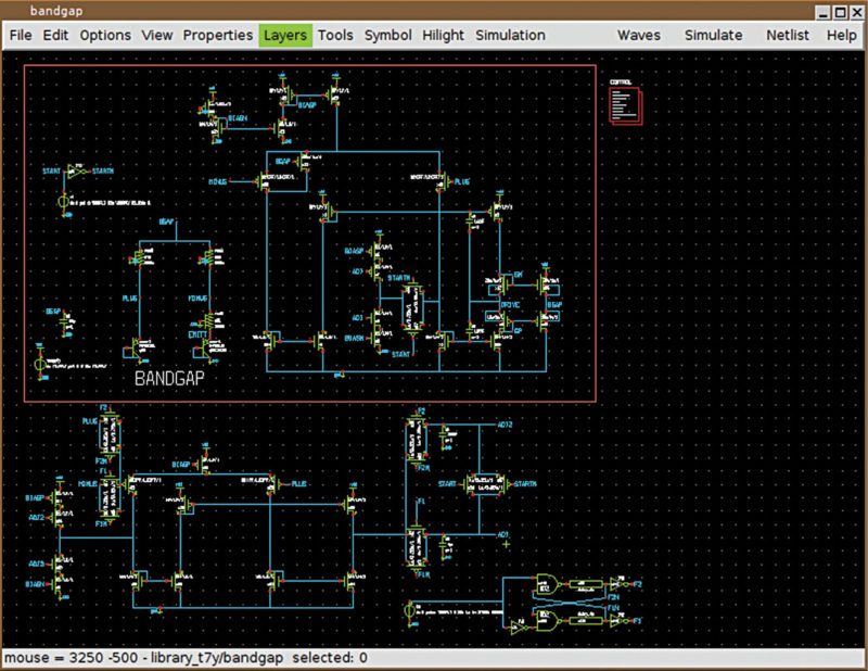
Although the user interface looks very simple, the net-listing and rendering engines in XSCHEM are designed from the ground up to handle very large designs in the most efficient way. All you have to do is keep bind keys in your hands, as most of the work is done by these. This comes in very handy when working on bigger projects that combine more than 1000 transistors and still use context menus and elaborate graphical actions while designing these.
Start designing using layers
Most editing commands are available in the menu, but definitely key bindings and mouse actions are the most effective ways to build and arrange schematics, so you should learn at least the most important ones.
Properties are text strings that are associated with XSCHEM objects. All graphic primitives such as lines and wires, which could be combined to create more complex graphical images, are supported. These are:
• Wires
• Lines
• Rectangles
• Texts
Consider, for example, res.sym symbol (you may open it with Open menu). If you click on one of the red pins and press edit property bind key q, a dialogue box shows the property string associated with the selected pin.
Wire layer.
Wiring is one of the most important aspects of an electrical design. In this software the wires are said to be equivalent of copper traces found in printed circuit boards or electrical conductors. The wires can be drawn as lines while the electrical connectivity graph is built by the software itself. If you wish to draw a wire segment, all you have to do is point the mouse somewhere on the drawing window and press w key.
It could be seen that an elastic wire image appears with one end following the mouse cursor. By clicking the left mouse button, the wire could be brought to the place where it needs to be finished. XSCHEM has an advanced way of recognising the connection of wires, and uses this information to build circuit connectivity. Hence, all wires are drawn from the wire layer.
Text layer.
It is easy to place text on the design pane. All you have to do is use shortcut bind key t to enable text feature. This opens up a dialogue box, which appears where you can provide inputs as text and determine text size.
Line layer.
While using XSCHEM you will get familiar with layers as every component in the design is part of a layer. Every layer has its own characteristic like colour and hierarchy. Lines in this software do not have any electrical meaning and are just segments for drawing lines. XCHEM has provisions that make lines look like wires, which could be implemented using bind key l.
Rectangles layer.
While drawing rectangles, again on multiple layers, a specific PIN layer is used to make pins that are used to interconnect wires and components. Rectangles are placed with bind key r on the design screen.
The whole nine yards of XSCHEM simulator
To create a new circuit, start at an empty window—all you have to do is run XSCHEM and select New in File menu. If you wish to place a NAND gate, with two inputs A and B, and one output Z, all you have to do is place the input and output schematic pins, later using Insert key, and locate the devices using symbols.
Editor that commands all.
Principles of a design are governed by the circuit that is being created by you. With XSCHEM you can also decide what to do with a selection. If you decide to change the property of a selected object, a simple press of property key q does the job.
Now there is more emphasis given to the bind key. Multiple objects could be moved using multiple clicks and holding onto shift key while pressing on m key. You can find almost all editing commands available in Editor menu. With interactive icons on the editor, mouse actions and keyboard shortcuts, it is easy to build complex schematics in very little time.
Net-listing and pre-designed modes.
To help better the designs, XSCHEM is bundled with three pre-defined net-listing modes. These are SPICE, Verilog and VHDL. Each net-listing mode opens to an Options menu complete with VHDL, Verilog and SPICE radio buttons. You can select through the netlist modes, which are found on the top-right part of Menu bar.
Net probes and colour highlighters.
XSCHEM has the ability to highlight nets and propagate the highlight colour to all nets or instance pins attached to the net. With this feature, it becomes really easy to net through the hierarchy, and there is greater visibility while working with large and complex designs. Click a net and press k key, and the highlighter comes to life.
Final simulation.
The software fulfils almost all design goals of optimally launching simulation without additional manual file editing. XSCHEM accomplishes this by storing not only the schematic of the circuit but the simulator settings including all additional files.
Schematic-ready simulations could be made ready just by clicking Simulation button. Icarus Verilog simulator gets executed to compile (iverilog) and run (vvp) the simulation. Finally, a terminal window will show the simulation output.