


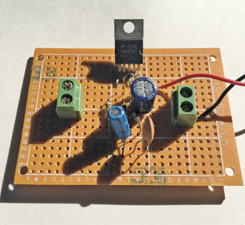
 Here is a simple 10-watt audio amplifier using IC LM1875. The IC has five pins and can deliver a maximum of 18-watt output power depending upon the supply voltage and load. The author’s prototype is shown in Fig. 1.
Circuit and working
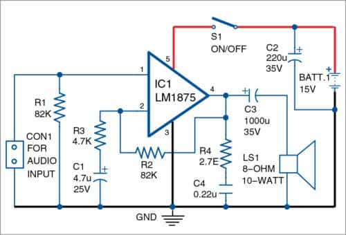
The circuit diagram of the audio amplifier is shown in Fig. 2. It is built around popular amplifier LM1875 (IC1), an 8-ohm, 10-watt speaker (LS1) and a few other components.
Connect the audio input from your mobile/laptop/PC to CON1. Connect 15V battery and switch on S1. You should hear amplified sound in speaker LS1.
Construction and testing
Use a 25-watt soldering iron for soldering LM1875 and other components. A 2-pin connector should be used for input and output connections to make the prototype safe and clean. Use a suitable heat-sink for LM1875 to prevent its overheating.

A PCB layout for the amplifier is shown in Fig. 3 and its components layout in Fig. 4. After assembling the circuit on the PCB, enclose it in a suitable box. Fix LS1 on the rear side of the box.
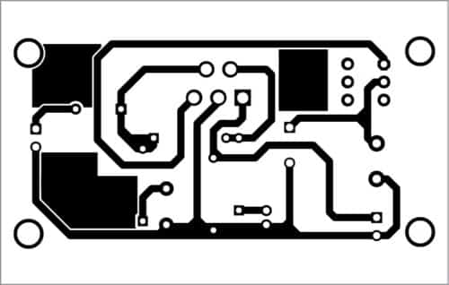
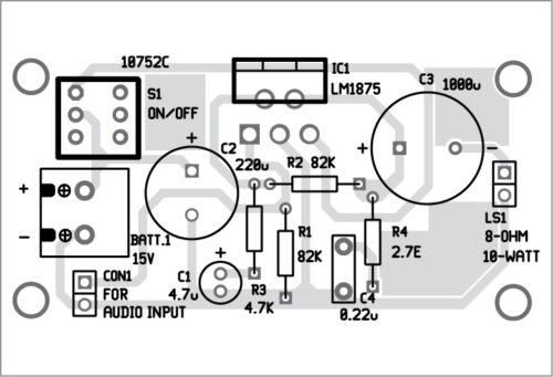
Download PCB and component layout PDFs: click here
For testing the circuit, connect a 6V battery to this circuit along with an 8-ohm, 10-watt speaker.
Take a metal screwdriver and gently touch at the input terminal. If your prototype is working, you will hear a humming sound from the speaker. You may connect a 100-kilo-ohm potmeter between audio input and ground and middle pin of potmeter to pin 1 for volume control. Your circuit is now ready to use.

You can use the power supply from a 5V to 15V battery, which will give you clear and noise-free audio signal output.
Raj K. Gorkhali is a regular contributor to EFY. His interests include designing electronics circuits.

Sir i need help from u can i get your email??
This circuit is not working. The circuit in the datasheet has a voltage divider consisting of two resistors but here only one resistor is connected at input pin 1. Also, a single supply configuration won’t g higher power even at 2 Ampere supply.
This circuit is not working as there should be a voltage divider network at pin 1 of the IC. Also, it can’t give 10 Watts at Single supply of 15 Volts since it’s designed to work properly on Split supply. I have constructed the circuit according to datasheet and it gives only 2 Watts max at 22 Volts, 2 Amp transformer
Hello sir, can’t i just make the circuit without those resistors, only just a couple of those capacitors?
The author of this article hasn’t done a correct job with the LM1875. According to the datasheet for a single power supply, refer to page 3 of http://www.ti.com/lit/ds/snas524a/snas524a.pdf. Anirvan was correct to mention that there is a voltage divider at pin 1.
The schematic on P3F2 uses a different topology than the schematic here. Do not try to combine them, or add a second resistor like the datasheet (except to the schematic on this page), or it will not function. The schematic here uses a voltage feedback topology to set the gain whereas the P3F2 schematic uses a resistor shunted between a voltage divider between the supply voltage and ground to set the gain (with that second resistor you refer to). So adding that second resistor here and shunting it either between a VCC-GND voltage divider, or tying it to VCC or GND will cause this schematic here not to function. So you should build the schematic here as shown, and it should function just fine 🙂
where is the variable resistor to change out put audio
This guy need to go back to school, this circuit will NOT work as others have said, for a single ended supply the input needs to be biassed to half the total supply so the output at pin 4 is around 12.5V for a 25V supply…… plus there is no DC isolation capacitor on the input – bad idea!
If you want a working circuit use the LM1875 data sheet
The prototype sent to us by author was working fine. However, for better performance your point is correct. Its always better to follow the datasheet. Waiting reply from author.
Good amplifier. Very low THD for such a high power. But National Semiconductor was acquired by Ti and now available under Ti brand name.