


The scale, with a 24-bit range and a 16-bit DAC, offers precision in industrial measurements, featuring user-programmable calibration and varied sensor supply options.
Weigh scales are a cornerstone tool in various industrial applications that measure mass. These scales range in capacity, accurately assessing everything from minuscule amounts of reactants in chemical processes to the weight of large cargo containers. This functionality is integral in conducting precise chemical reactions and effective commodity management, underscoring the importance of weight scales in many industrial contexts.
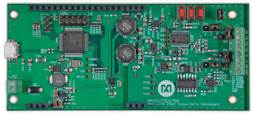
Analog Devices has launched a 24-bit weight scale with a 16-bit Digital Analog converter (DAC), MAXREFDES75, to simplify the design process. The design can perform precise small-signal measurements of plus or minus twenty-five millivolts full scale. Additionally, it generates a high-voltage sensor supply and produces an output ranging from 0 to 10 volts, proportional to the input signal.

The reference design is equipped with several key features. It offers ratiometric measurement capabilities, meaning it can measure relative to a precision voltage reference. It allows user-programmable offset and gain calibration for both the sensor (load cell) and the DAC for enhanced versatility. Additionally, users can program the output voltage range, mapping it according to specific requirements. This design provides a flexible and customizable approach to measurement and calibration.
The design offers various options for sensor supply, allowing 10V or 3.3V to power the load cell. Using 10V for excitation leads to optimal performance but adds more components and increases the cost in the final design. On the other hand, the 3.3V rail, essential for the operation of the ADC, is always available. The ADC can work in a ratiometric mode, utilizing either a reference-derived resistor divider from the 10V rail or the MAX6126 voltage reference. While the ratiometric method is usually preferred, the voltage reference allows users to test the system without the gain variations induced by the system setup.
The board is powered by a single DC source from 9V to 40V, 200mA, connected through the X2 terminal block. The MAX17501 chip converts the variable input supply to a +8V rail. The MAX16910 Low Dropout Regulator (LDO) generates 3.3V for the MAXQ622 from this 8V rail. The MAX13256 chip provides isolated positive and negative rails for the ADC, DAC, voltage reference, load cell, and analogue output. The MAX16910 LDO also supplies VDD for the MAX542, while the MAX8510 LDOs produce AVDD and DVDD for the MAX11270. Finally, the MAX9633 chip creates a low-noise 10V supply for the load cell.
Analog Devices have tested this reference design. It comes with a Bill of Materials (BOM), Schematic, etc. You can find additional data about the reference design on the company’s website. To read more about this reference design, click here.