


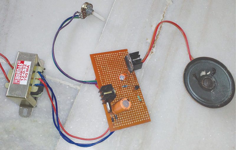
Audio amplifier circuits commonly use single-chip audio ICs like LM384 and LM386. These circuits look very easy to assemble but require additional components like resistors, capacitors and sometime inductors. Here we present the circuit of a single-chip 3W audio amplifier using TDA7056 that only requires two capacitors for biasing and one potmeter for volume control (and that’s also optional). You also need to connect a 3W, 16-ohm (or 1W, 8-ohm) speaker at the output of the circuit. So when an audio signal is applied to the input, you can hear the amplified output from the speaker. The author’s prototype is shown in Fig. 1.
The main features of TDA7056 include:
1. Bridge-tied load working principle
2. Supply voltage range of 3V to 18V
3. Gain of 40dB
4. No external components required
5. No switch-on or switch-off clicks
6. Good overall stability
7. Low power consumption
Working on bridge-tied load principle, the circuit can output 1W power into an 8-ohm load with a power supply of 6V, and 3W power into a 16-ohm load with a power supply of 12V.

Audio amplifier circuit and working
Fig. 2 shows circuit of the 3W audio amplifier using TDA7056 (IC4). It has two sections: power supply and amplifier.
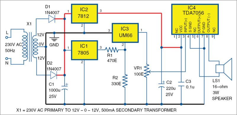
Power supply.
Here the AC mains power supply is stepped down using transformer X1, rectified by a full-wave rectifier comprising diodes D1 and D2, filtered by capacitor C1 and fed to 5V voltage regulator 7805 (IC1) and 12V voltage regulator 7812 (IC2) to maintain constant +5V DC supply for melody generator UM66 (IC3) and +12V DC supply for audio amplifier TDA7056 (IC4), respectively.
Amplifier
The amplifier section is built using two chips: melody generator UM66 and audio amplifier TDA7056. Melody generator chip UM66 (IC3) is used to provide audio input to the amplifier. It requires around 3V input. So a voltage divider network using resistors R1 and R2 is used to derive 3V from 5V output of the power supply. The output of IC3 is connected to the positive input of TDA7056 through a 100-ohm potmeter used for volume control.
Vcc pin of IC4 is connected to 12V supply along with two capacitors as shown in Fig. 2. The 3W, 16-ohm loudspeaker is connected to output pins 6 and 8 of IC4.
Construction and testing
An actual-size, single-side PCB layout for 3W audio amplifier using TDA7056 is shown in Fig. 3 and its components layout in Fig. 4.
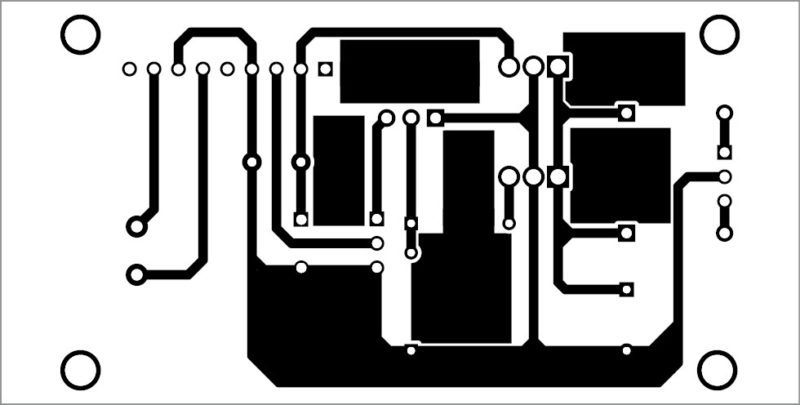
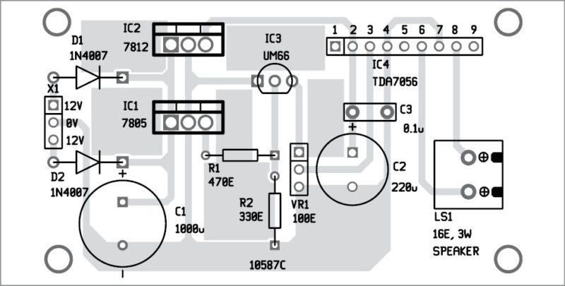
Download PCB and component layout PDFs: click here
After assembling the circuit on the PCB, enclose it in a small box. Place transformer X1 and speaker inside the box.
When you switch on the mains power supply, UM66 chip gets activated and it generates a melody tone, which is fed to TDA7056 through potmeter VR1. TDA7056 chip amplifies the melody sound to around 3W, which can be heard from the speaker. By varying VR1, you can adjust the volume of the output tone.
Feel interested! Here are some circuit ideas.
Superrr&thank you
You are most welcome.
where did u got that ic 7056??
thanks alot
You are welcome.