


Here is a simple FM radio receive which is built around 18-pin IC AN 7223. You can tune to frequency around 88.00MHz-108.00Mhz from this FM radio receiver.AN 7223 can be easily purchase in a market and it cost is not expensive. Most FM radio was works on 10.7MHz IF frequencies and uses 10.7MHz IFT coil and 10.7MHz Ceramic filters. As a 10.7MHz IFT coils are not found easily. So, here i use 5.5MHz IFT coil and 5.5MHz ceramic filter which can be easily available.
Circuit Description
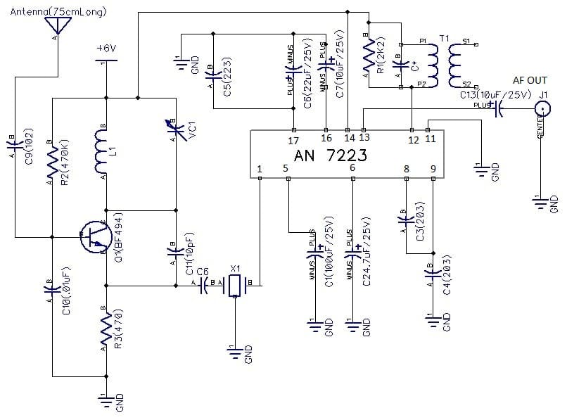
Only one NPN transistor BF494 and one Intergrated circuit AN 7223 (18-pin) are used in this circuit. Few external components like coil, 5.5MHz IFT coil,5.5MHz ceramic filter, resistors, ceramic capacitors, trimmer capacitor (2-22pF) were used.
Capacitor C1 (100uF/25V) is connected to ground with its negative terminal and positive terminal to pin 5. Capacitor C2 (4.7uF) is also connected to ground with a negative terminal and positive terminal to pin 6 of AN7223.

Capacitor C3 (203) is connected between pin 8 and pin 9 of AN 7223.Capacitor C4 (203) is connected to pin 9 of AN7223 and ground. Pin 11 is connected to ground.
Pin 12 of AN7223 is connected to +6Volts through a 5.5MHz IFT coil. A resistor R1 (2K2) is connected between a 5.5MHz IFT coil. Pin 14 of AN 7223 is connected to +6Volts.
Pins 16,17 are also connected to ground through an electrolytic capacitors C6(22uF/25V), C7 (10uF/25V). A capacitor C6 is connected between ground and pin 17.
An audio output is taken out from pin 13 of AN 7223 through an electrolytic capacitor C13 (10uF/25V) from a 2-pin connector.
Resistor R2 (470K) is connected between a base of Q1 (BF494) and +6Volts. Resistor R (470) is connected between ground and emitter of Q1 (BF494). Coil L1 is connected in parallel with a VC1 (2-22pF) and connected to + 6Volts and collector of Q1 (BF494). Capacitor C11 (10pF) is connected between an emitter and collector of Q1.Capacitor C10 (.01uF) is connected between base and ground.
Construction and Calibration
Capacitor C12(33pF) is connected between an emitter of Q1 and to an input terminal of a 5.5MHz ceramic filter and to a pin 1 of IC1 (AN7223). An antenna of 75cm long wire is connected to a base of Q1 (BF494) through a capacitor C9(102).
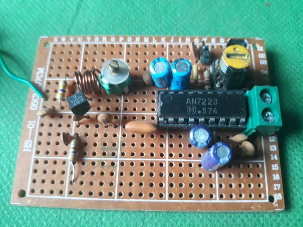
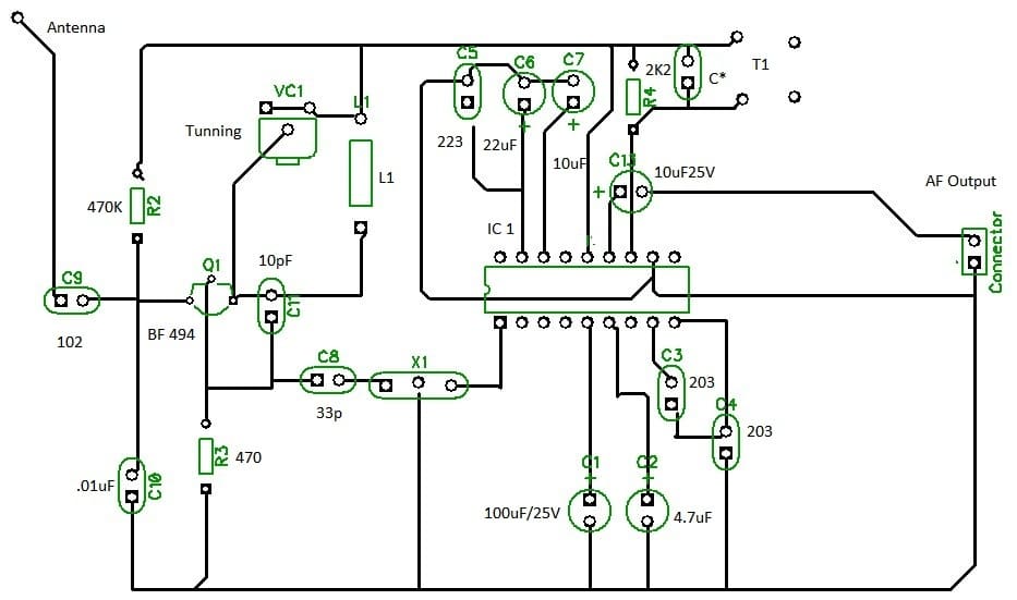
After inserting all the components take a 25W soldering iron and solder all the components. Don’t insert an IC on a IC socket while soldering IC socket on zero PCB.Before we construct this radio we will make a coil L1 of 5 turns of 23 SWG wire on a 5mm air core.
Take a piece of 23 SWG wire and remove its enamel on two ends. Now take a 5mm drill bit and gently wound 5 turns of 23 SWG copper wires.
Now take a 18-pin IC socket and place it on a middle of a board. You may also use a zero PCB (5cm*7cm).
Place a transistor Q1 on a left side of a zeroboard and 2-pin connector to a right side of a zero board.
Take a 5.5 MHz IFT coil and connect it in parallel with a resistor R1 (2K2).Now connect them to a pin 12 of IC1 and +6 Volts.
For a calibration you will need a low power Audio amplifier. Here i used a LM 386 AF amplifier.
Connect a speaker and connect it an AF amplifier. Also connect a +6 Volts to an AF amplifier.
Now connect an output (2-pin connector) from your FM radio to an input of AF amplifier.
Connect 4* 1.5V AA battery or 6 Volts battery to your FM radio receiver. You will hear a hissing sound comming out from a speaker of an Audio amplifier.
Gently tune a VC1 trimmer capacitor or adjust a coil L1 by pulling towards. You will hear many stations.
Adjust a core of 5.5MHz IFT coil until you hear a clear station coming out from your FM radio.So, your FM radio is working and ready for listening.
Parts-List
| Semiconductors |
| Q1: BF494 |
| IC1: AN7223 |
| Resistors |
| R1: 2K2 |
| R2:470K |
| R3: 470 |
| Capacitors |
| C1: 100uF/25V |
| C2:4.7uF/25V |
| C3, C4:203 |
| C5: 223 |
| C6: 22uF/25V |
| C7:10uF/25V |
| C9:102 |
| C10:.01uF |
| C11:10pF |
| C12:33pF |
| C1310uF/25V |
| X1:2-pin 5.5MHz Ceramic filter |
| T1: 5.5 MHz IFT coil |
| VC1: 2-22pF Trimmer |
| Micsellaneous |
| 2-pins connector |
| 8-pin IC socket |
| 5cm*7cm Zero PCB |
