


High-voltage eFuse innovation, safeguarding users and hardware with remote control and CAN bus integration, is reshaping power protection for the future.
With the rise in high-voltage eMobility applications, semiconductor-based resettable fuses swiftly supplant traditional mechanical relays/contactors and non-resettable fuses. The emergence of eFuses represents an innovative trend in safeguarding users and hardware in high-voltage/power scenarios. Vishay has introduced a reference design featuring an eFuse equipped with SiC MOSFETs and a VOA300 optocoupler designed to handle continuous power loads of up to 40 kW. This design operates continuously at full power with minimal losses (less than 30 W) and no need for active cooling but also incorporates essential features such as a preload function, continuous current monitoring, and rapid overcurrent protection.
The design is purpose-built to manage the connection and disconnection of a high-voltage power source, typically a high-energy battery pack, to various vehicle loads safely. This is achieved using SiC MOSFETs as the primary switches, capable of continuous operation at up to 100 A currents. If the current surpasses a predefined limit, the eFuse rapidly disconnects the load from the battery pack, safeguarding both the battery pack and the user. Additionally, the eFuse can detect excessive load capacitance or a short circuit during the power-up phase and immediately initiate a shutdown.

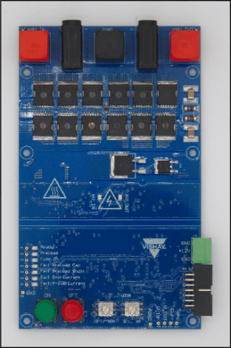
The eFuse is constructed using a standard double-sided four-layer PCB, each featuring 70 μm thick copper. The overall dimensions of the PCB are 150 mm × 90 mm, with some connectors extending beyond the edges. On the top side of the PCB, you’ll find the high-voltage circuitry, connectors, control buttons, status LEDs, and multiple test points. Meanwhile, the low-voltage control circuitry is on the PCB’s bottom side. Additionally, the eFuse can be controlled remotely via a web browser.
To ensure safety, the low-voltage power supply must be enabled first, followed by the high-voltage power supply on the input. An LED indicator illuminates when the voltage at the input terminal exceeds 50 V. To ensure the eFuse can handle currents in both directions, it employs two sets of six SiC MOSFETs connected in parallel in a back-to-back configuration. The current passing through the load is monitored via a Vishay WSLP3921 current-sensing shunt resistor strategically positioned between these two sets of MOSFETs.
Moreover, the eFuse offers convenient control options, allowing users to operate it via the onboard PCB buttons or the Vishay MessWEB external controller, unlocking access to an expanded array of features. Additionally, seamless integration of the eFuse into a CAN bus-based system can be achieved by utilizing the MessWEB in conjunction with an additional chipset.
Vishay has tested this reference design. It comes with a Bill of Materials (BOM), schematics, etc. You can find additional data about the reference design on the company’s website. To read more about this reference design, click here.