


Zener diode is a silicon semiconductor device that permits current to flow in either a forward or reverse direction. The diode consists of a special, heavily doped p-n junction, designed to conduct in the reverse direction when a certain specified voltage is reached. The zener diode has a well-defined reverse-breakdown voltage, at which it starts conducting current, and continues operating continuously in the reverse-bias mode without getting damaged. Additionally, the voltage drop across the diode remains constant over a wide range of voltages, a feature that makes zener diodes suitable for use in voltage regulation.
Most of the R&D units, educational institutions and industrial units are unable to test the Zener and ordinary diodes This DIY project Zener diode tester can be used for serviceability tests for Zener diodes and ordinary diodes. This instrument is designed with a resolution of 0.01V so it is useful to find out the matched pairs of zener diodes, in some critical circuits which require matched pairs of zener diodes.
The circuit is designed with the ATMEGA328 microcontroller IC. The standalone Arduino technique is adopted here because of the popularity, economical, and easy-to-use features of Arduino IDE. This instrument can be used to test the zener diode up to 33V.

Circuit and Working
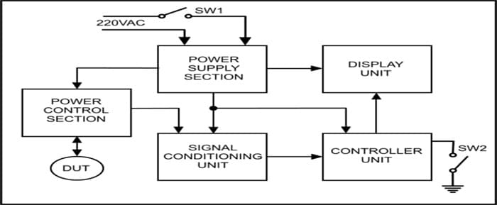
Fig 1 shows the block diagram of the project. The design has five sections:-
- Signal conditioning unit
- Microcontroller
- Power section
- Power control
- Display unit
The detailed description of the components and modules of each section as per the circuit diagram are explained below:
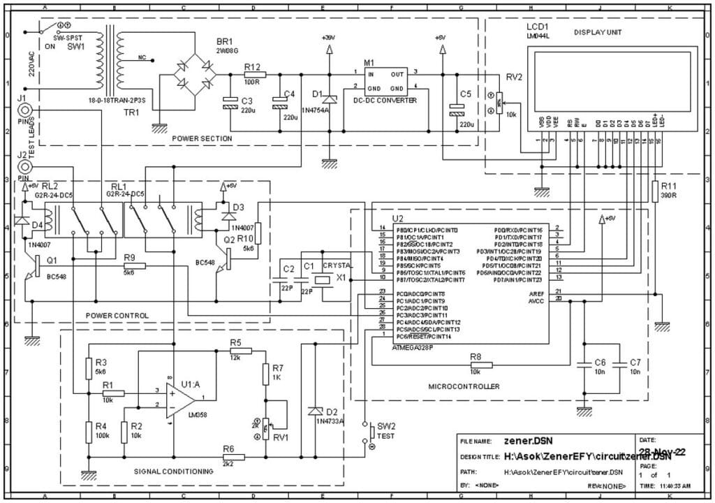
- Power supply section: The power supply section provides the required supply voltages for the smooth working of the circuits. The transformer TR1. Converts 230VAC supply to 36VAC. The bridge rectifier (BR1) rectifies the AC to DC. C3, C4, C5, and R7 are connected as π filter. The capacitor C5 is connected across the DC-DC converter output as an additional filter. The Module M1 U3 is a dc-dc converter that is used to convert high voltage DC to constant 5V output. Please refer to the datasheet for more information. The main advantages of this are the high input voltage (up to 40V) and very high efficiency. The 5V output of this circuit is connected to the controller and display section.
- Power control section: This section mainly has two relays RL1 and RL2, transistor Q1, Q2 diode D3, D4, and resistor R9, R10. This RL1 and associated circuit are provided to switch ON the power supply to the signal conditioning section only when the test switch is depressed. The RL2 and associated circuits will toggle the supply voltage of the test probe after a predetermined delay as per the software.
- Signal conditioning unit: The signal conditioning unit converts the more zen voltage to a safe level for measuring using Arduino. This section of the circuit consists of one Op-Amp (U1), trim pot (RV1), and resistors R1 to R7. The resistors and variable resistors are connected as potential dividers to the Op-Amp. This section converts the voltage drop across the D.U.T (Diode Under Test) to a 0 to 5V linear ratio. The Op-Amp is connected as a voltage follower and will be used to get maximum linear output voltage by utilizing the high input impedance characteristics of an op-amp.
- The Controller Unit: This section is the most important part of the circuit. The ATMEGA328 (U2) is an 8-bit AVR microcontroller with six inbuilt Analog to Digital Converter (ADC), six Digital to Analog Converters (DAC), and 12kb flash memory. The reason for selecting this IC is it can be programmed using Arduino which is known as the most popular and economically viable software development platform. This section has few components connected to U2 to work as a standalone Arduino. The resistor R8 used for power on reset. The crystal CR1 Capacitors C1 and C2 are the oscillator circuits. C6 and C7 are for filter capacitors and should be connected as near as possible to the supply pins of the controller.
- Display unit: The LCD display (LCD1) is a 20X4 alphanumeric LCD display which will show all the instructions for testing, and the test results. The trim pot RV2 can be used to adjust the contrast of LCD.
The purpose of the diodes D3 and D4 which are connected in parallel to a relay coil (flywheel diode or freewheeling diode) is to avoid damaging some nearby components sensitive to high voltage. This voltage is generated in the coil when the current flow is interrupted. The switch-S2 is connected to the controller to start the test.
The D.U.T is connected in parallel with R4 of the potential divider R3 and R4. The voltage drop across the D.U.T is connected to non-inverting input of the voltage follower the voltage will be available at the output. The maximum output voltage is restricted to 0 to 5V for an input of 0 to 36V. This signal conditioner is connected to the microcontroller ADC (A0). The controller measures the ADC input and displays formulated data. On power up the device will scan the test switch status and LCD shows the required instructions. A momentary pressing of the test button will start the main test program.
Initially, the system will measure voltage drop across the D.U.T and data will be stored. After two seconds the relay RL2 will energize to toggle the polarity of test leads and measure the voltage drop. The system will process both data and display the test results as type of diode, forward voltage, reverse voltage and the result (serviceable/defective). After completion of the test the supply to the test lead will disconnect automatically and unit will divert back to standby mode. The user can edit the software to add different types of diodes according to their characteristics by referring the data sheets.
Software
Software is written in Arduino ”C” language. The working of the software is well explained in the program itself. Special libraries used in software such as Liquid cystalI2C.h. Installation process of the third party header files available in www.arduino.cc.
Construction and Testing
Download file Source compile sketch using Arduino IDE. Connect Arduino UNO to PC, select the proper port and board. Upload the sketch. Ensure that the Sketch is compiled without errors.
Assemble all the components on PCB as shown in PCB designs. Make all the wiring as per the circuit diagram. Cross check for any wrong connections. Remove the programmed ATMEGA328 IC from Arduino and insert the on the IC socket. Ensure the proper orientation of the IC before inserting, improper orientation will damage the chip.
Switch ON 230V power supply, ON the switch SW1 the LCD will lit up and LCD will show the welcome messages as written in the software, If not adjust the RV2 to set the contrast of the LCD. Connect an ordinary diode across the test leads and press the test button. The system will measure the forward and reverse voltages. The final result will be displayed on the LCD screen. The system will divert back to standby mode after few seconds as assigned in the software.
Zener Diode Tester – Components List
| Resistors | Capacitors |
|
R1,R2,R8- 10k
R3, R9, R10– 5k R4-100k R5-12k R6-2k2 R7-1k R11-390R R12-100R/0.5W RV1 2k Square TRIMPOT RV2 10K Square TRIMPOT |
C1,C2 – 22pF- Ceramic Disc
C3,C4,C5- 220 uF/63V Radial Electrolytic C6, C7 – 10nF Ceramic Disc |
| Integrated Circuits | Diode |
|
U1- LM 358
U2- ATMEGA328P (with Arduino Boot loader) |
D1-1N 4764A – 39V Zener Diode
D2- 1N 4733A – 5.1V Zener Diode D3, D4- 1N4007 |
| Switch | Terminal |
|
SW1 – SPST Switch
SW2 – Push Button Switch |
J1-J2 : Test Points
|
| Transistor | Miscellaneous |
|
Q1,Q2 – BC 548
|
X1- 16MHz crystal,
TR1- 18-0-18 1A Transformer LCD1- 20 x 4 LCD Module M1- 5V DC-DC Converter Module |
| Relay | |
| RL1, RL2 5V DPDT PCB Mountable |
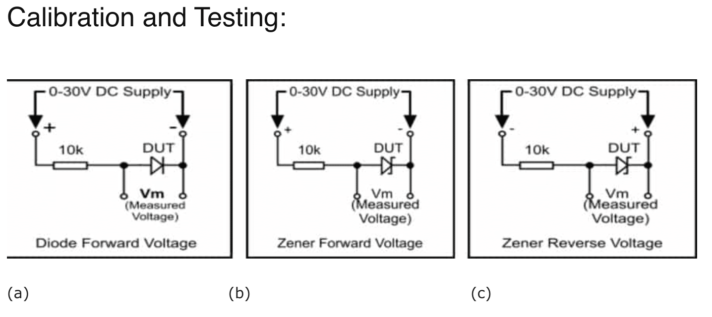
Collect one serviceable ordinary diode and a 27V zener diode. Connect a 10k Resistor in series with the ordinary diode as shown in Fig-3(a), slowly increase the voltage to get a steady voltage across the diode Measure the forward voltage drop of the diode. Measure voltage drop using a calibrated multi-meter. Record the readings. Connect a 10k Resistor in series with the 27V zener diode as shown in Fig-3(b), slowly increase the voltage to get a steady voltage across the diode Measure the forward voltage drop of the zener diode, reverse the DC supply polarity as shown in Fig-3(c) and repeat the process.
Measure the reverse voltage drop using a calibrated multi-meter. Record the readings. Connect the diode across the test leads and press SW2. Record forward voltage drop. Connect the 27V zener across the test leads and repeat the process, record both readings. Compare the displayed readings (diode forward voltage drop, zener diode forward and reverse voltages) with the recorded readings. If the displayed voltage are same as the recorded voltage, no calibration is required. Else adjust RV1 slowly and repeat the test to get satisfactory readings.
Note
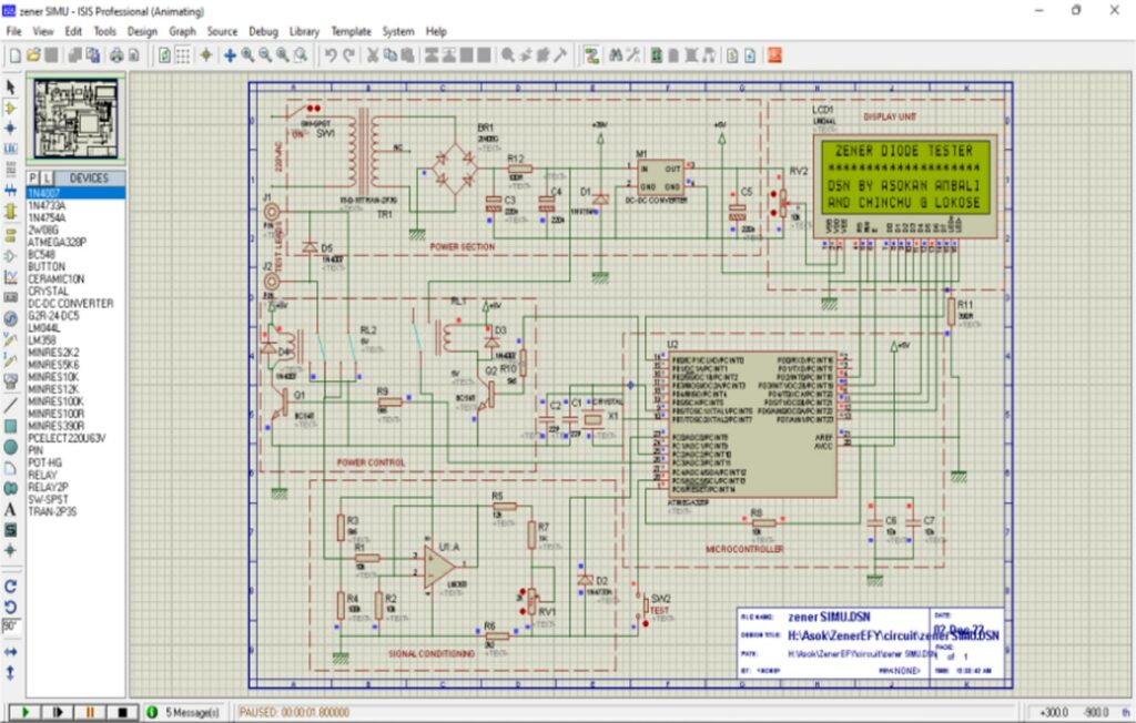
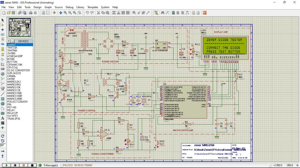
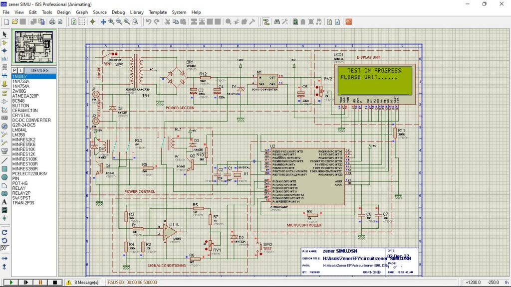
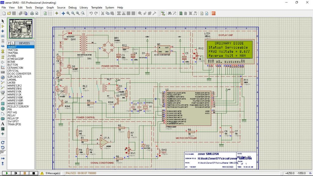
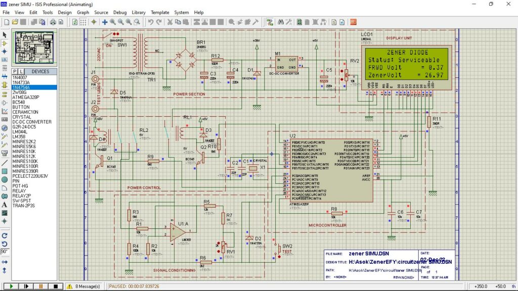
The entire circuit is successfully simulated in a proteus design suit and the results are found satisfactory. The screenshots of the simulations for different diodes are shown below-
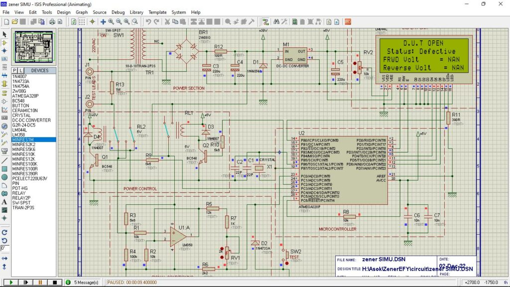

Author: Asokan Ambali

Fig2. Zener Diode D2 connection is shorted.
Dear Sir,
Thanks for pointing. Corrected Fig.2.
Regards
Hello. I couldn’t find the software to install ATMEGA328? . I’m asking because I don’t know, is the Arduino set used to install the ATMEGA328 software? Thanks.
Dear Ihsan,
Yes Arduino board may use to program Atemga328. Follow the steps given below:
1. Download and Install Arduino IDE: If you haven’t already, download and install the Arduino IDE from the official Arduino website (https://www.arduino.cc/en/software).
2.Configure Arduino IDE for ATmega328: Open the Arduino IDE, then go to File > Preferences. In the “Additional Board Manager URLs” field, add the following URL:
bash
Copy code
https://mcudude.github.io/MiniCore/package_MCUdude_MiniCore_index.json
Click “OK” to close the Preferences window.
3. Install ATmega328 Board Support: Go to Tools > Board > Boards Manager…. Search for “MiniCore” and install it.
4. Select ATmega328 Board: Now, you should be able to select the ATmega328 board variant you’re using. Go to Tools > Board and choose the appropriate ATmega328 option (e.g., “ATmega328”).
5.Select Processor and Clock: After selecting the board, choose the appropriate processor and clock speed under Tools > Processor and Tools > Clock.
6.Select Programmer (if using external programmer): If you’re using an external programmer (e.g., USBasp), select it under Tools > Programmer.
7.Connect and Upload: Connect your ATmega328-based board to your computer via USB. Write your code in the Arduino IDE, then click the upload button to compile and upload the code to the ATmega328.
Regards
Dear Suresh. I am grateful to you for responding. Thank you very much for your help. I will let you know when I complete the work. I wish you health and well-being.
Hi Suresh. I couldn’t make the circuit as a PCB and couldn’t figure it out. I ask you, if possible, can you share the PCB design? I can use .lay or .lyt. Thank you very much.