


Most computer UPS have only 230V output and no USB output. Presented here is a USB power circuit that gives 5V USB output using the 12V, 7Ah UPS battery fitted inside a UPS. With this circuit you can power USB gadgets directly from a UPS without turning on the PC. This circuit can also be used to power development boards like Arduino and Raspberry Pi.
Circuit and working
As shown in Fig. 1, the circuit is built around switch-mode regulator LM2576-5V (IC1). The LM2576 series offers a high-efficiency replacement for popular three-terminal linear regulators. It substantially reduces the size of the heat-sink; in some cases, no heat-sink is required. It provides all the active functions of a step-down (buck) switching regulator, capable of driving up to 3A load with excellent line and load regulation. The 5V version of LM2576 (LM2576-5V) is used in this circuit.
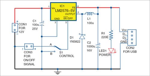
The 12V battery is connected to CON1. IC1, along with inductor L1 and diode D1, steps down and converts the 12V input into 5V output. Capacitor C2 reduces ripples in the output. Feedback pin 4 of IC1 is directly connected to the output at C2.
IC1 can be turned on/off by an external control signal or else it can be turned on permanently by grounding pin 5 of IC1 through switch S1. When S1 is in position A, IC1 can be controlled by connecting an external control signal at CON3. When S1 is in position B, IC1 is switched on permanently. LED1 indicates whether IC1 is on or off. This circuit can be used to power gadgets digitally.
Construction and testing
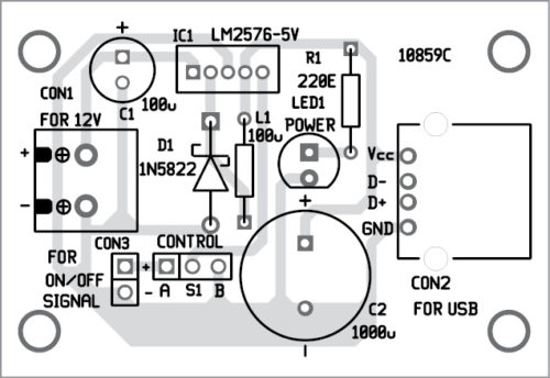
A PCB layout for the add-on USB power circuit for a UPS is shown in Fig. 2 and its components layout in Fig. 3. Assemble the circuit on the PCB and place it at a suitable location inside the UPS.
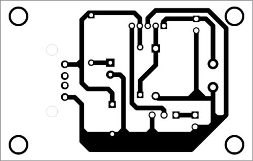
Download PCB and component layout PDFs: click here
Use suitable heat-sink for IC1. Inductor L1 must have a minimum current rating of 1A. Capacitor C2 should have low equivalent series resistance (ESR) for better performance. Any voltage from 7-40V can be used for the circuit.
If the external control signal is open-collector type, a suitable pull-up resistor must be used on pin 5 of IC1. Do not leave this pin float. To maintain stability, capacitor C1 leads must be kept short and placed near IC1.