


 This article highlights common errors in 8-bit instruction sets, and introduces a novel architecture for decimal conversion instructions, especially in 8051, 8086, 8085 and PIC microcontrollers (MCUs). Statistical analysis of different methodologies has revealed that decimal conversion instructions in microprocessors and MCUs do not offer an error-free process. Bugs can be common for the above-mentioned MCUs. The algorithms discussed in this article have been tested for various platforms and offer accurate results on all 8-bit MCUs and microprocessors.
Binary-coded decimal number system
Binary-coded decimal (BCD) numbers are used to represent digital numbers, that is, zero to nine. In computer language, there are two terms used for BCD numbers: unpacked and packed. These two are shown in Fig. 1.
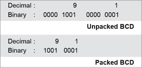
In another example, number 74 in packed BCD format would be 0111 0100, whereas, unpacked BCD format would be 0000 0111 and 0000 0100.

Unpacked BCD
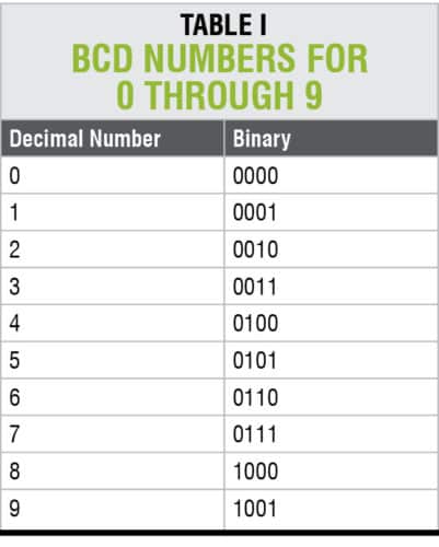
The lower four bits of the numbers represent BCD number. Only one byte of memory is required for unpacked BCD numbers or 8-bit register to contain it. In unpacked BCD numbers, upper bits are zeros (0s). For example, 0000 0001, 0000 0010, up to 0000 1001 are unpacked BCD numbers for 1, 2, … 9, respectively.
Packed BCD
In packed BCD numbers, a single byte has two BCD numbers, one in the lower four bits and the other in the upper four bits. Both lower and higher four bits are used. Only one byte of memory is required to store packed BCD operands. For example, 0101 0010 is packed BCD for 52H.
While adding two BCD numbers, the result must be a BCD number. If that is not the case, then it must be corrected by adding number 6 to it.
Computers use hexadecimal number system. If you add two BCD numbers 9 and 1, the result should be 10. But a microprocessor uses hexadecimal addition and gives the result as A instead of 10. Here, A is not a valid BCD number (BCD numbers are from 0 to 9).
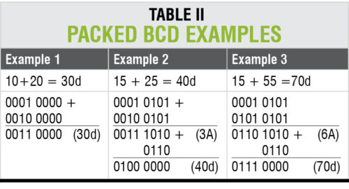
To solve the problem, add six to the hexadecimal number system (A, B, C, D, E, F). This is done by adding number 6 to the result to get the expected result. Consider the following examples to know the BCD conversion process, as given in Table II.
In the first example, lower and upper nibbles of the sum of 10 and 20 lie in the range of 1 to 9. So, in this case, conversion procedure is not required.
In the second case, sum of 15 and 20 is 3A. Lower nibble (A) of the result is not in the prescribed range (0000 0001, 0000 0010, up to 0000 1001). To obtain the BCD result, add number 6 to the result. The required result is 40.
The same can be applicable to the third example, too.
DA instruction
DA, or decimal adjust, is an instruction used in 8051 MCUs for DA operation after addition operation like ADD A, R0, ADC A, R1, SUB A, R0, SUBB A, R1, etc. DA for addition instruction is designed to correct BCD addition problems. Like the decimal conversion discussed earlier, here too DA instruction adds number 6 to either lower or higher nibble, if needed. For detailed analysis, necessary conditions and procedures in DA instruction are explained below.
Working of DA instruction
- DA instruction is effective only after arithmetic operation.
- If lower nibble of result is greater than 9, or if auxiliary carry is 1 (AC=1), add 0110 in binary or 6H in the lower nibble to correct BCD problems.
- If upper nibble of result is greater than 9, or if carry is 1 (CY=1), add 0110 in binary or 6H in the upper nibble to correct BCD problems.
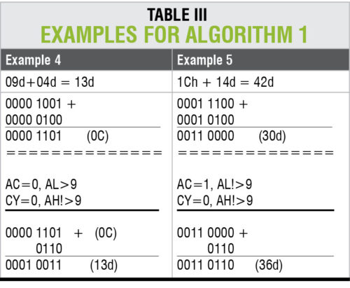
Algorithm 1 of DA A
IF ((A3-0 > 9) OR (AC = 1)):
{
A = A + 6 // or AL=AL+06
}
IF ((A7-4 > 9)) OR (CY= 1)):
{
A = A + 60h // or AH=AH+06
}
ELSE:
Nothing to be performed;
DA instruction works only on accumulator A (for example, DA A). This means that the source can be an operand of any addressing mode, but destination must be accumulator. BCD operand can never have any digit greater than 9. So, DA instruction must always be used after addition of BCD operands. DA instruction works after ADD/ADDC instruction in 8051.
To understand the functionality of DA A instruction, consider the following examples. For proper explanation, accumulator is logically divided into two sections—AL and AH—representing the lower and upper nibbles of the accumulator.
Consider example 4 given in Table III. Required output 13d is obtained in decimal form without any error. This conventional algorithm works as follows. After addition process, condition 2 of Algorithm 1 is achieved. So the compiler adds 6 to A or AL register to obtain the result, which is I3d.
In Example 5 given in Table III, required result is 42d after adding the binary for 1Ch and 14d. But, algorithm 1 failed because of the following reasons. After addition process, value of AL is not greater than 9 and AC=1. Step 3 of algorithm 1 is satisfied and AL register is added with 6. But in this process, decimal value is seen as 36d instead of 42d.
From the above analysis, it can be concluded that DA A instruction in 8051 does not work properly in some situations. Bugs can be easily corrected as shown in Algorithm 2. The algorithm is designed and tested in LabVIEW graphical programming platform.
Novel architecture of DA instruction
This modified approach on DA instruction offers an error-free decimal conversion process efficiently. The procedure for DA A instruction in 8051 MCUs is explained below.
- Compute the sum of the numbers using 8051.
- Take the value of AH as counter.
- Add 6d to AL register as many times as the counter AH registers.
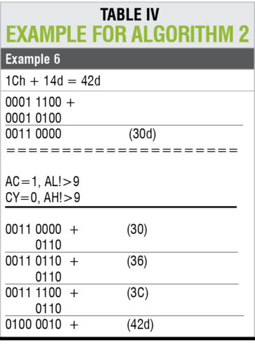
Consider the instruction for addition operation ADD A, B. Take test values from example 5 for this operation. Register A holds value 1C, and B register holds value 14. After adding 1C and 14, result is 30h.
As per Algorithm 2, load the counter with the value of AH register. In this case, AH is 3, so counter value will be 3. Addition of the number 6 three times (0 to 2) to AL register can be performed. The result obtained is 42. This is the correct expected result after application of Algorithm 2. Detailed steps of this explanations are shown in Example 6 in Table IV.
 Algorithm 2
IF (((A3-0 > 9) OR (AC = 1)) OR ((A7-4 > 9))
OR (CY = 1)):
{
Counter = AH;
While (COUNTER! =0):
{
AL=AL+6;
Decrement counter;
}
}
ELSE:
Nothing to be performed;
The above analysis shows that decimal conversion instructions in microprocessors and MCUs have problems. Any 8-bit arithmetic operation like addition and subtraction is sure to have problems.
Algorithm 2 has been tested, and it offers accurate results on all 8-bit MCUs and microprocessors.
K.M. Abubeker, Reeju Elisa Baby and Ajai Mathew are assistant professors at Amal Jyothi College of Engineering, Kanjirapally, Kottayam, Kerala.
