


 The automatic bike turning signal system based on a microcontroller (MCU) available in the market is expensive and difficult to program. Here is a simple and inexpensive circuit that you can build yourself.
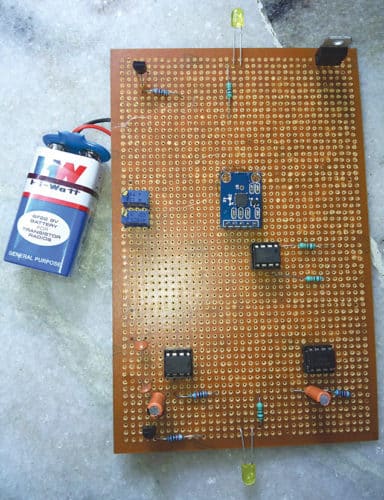
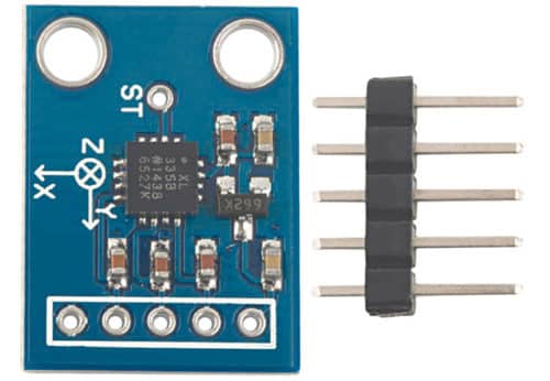
The circuit is used to indicate left or right turns for a bike or two-wheeler. Two identical circuits are needed, one for left and one for right. The author’s prototype is shown in Fig. 1, and the accelerometer sensor used in the project in Fig. 2.
Circuit and working for Automatic Bike Turn Indicator
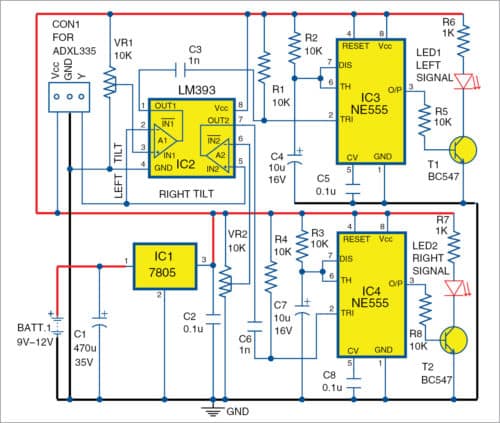
Circuit diagram of the bike turn indicator is shown in Fig. 3. The circuit consists of ADXL335 accelerometer sensor, voltage regulator 7805 (IC1), LM393 comparator IC (IC2), two NE555 timer ICs (IC3 and IC4) and a few other components.

ADXL335 is a small, thin, low-power, complete 3-axis (X, Y and Z directions) accelerometer with signal-conditioned voltage outputs. Only Y direction of ADXL335 is used in this project. The device measures acceleration with a minimum full-scale range of ±3 volts. It can measure static acceleration of gravity in tilt-sensing applications, as well as dynamic acceleration resulting from motion, shock or vibration.
Dual comparator LM393 is an 8-pin IC with pins 1, 2 and 3 forming one comparator and pins 5, 6 and 7, another comparator. The two comparators are used to monitor left turn and right turn indicator signals. Two NE555 timer ICs (IC3 and IC4) configured in a monostable multivibrator are used; one for left signal and the other for right signal. Here, 9V-12V battery is converted to +5V DC using voltage regulator IC (IC1).
Left signal
When the bike handle is turned to the left, it gives a tilt angle output in the form of 1.2V to 2.6V voltage. Inverting terminal (pin 2) of IC2 is connected to ADXL335 sensor’s Y signal, and non-inverting terminal (pin 3) is connected to preset (VR1). Pin 1 of IC2 outputs the left tilt angle signal.
Set reference voltage 2.2V at pin 3 using preset (VR1). Initially, when the bike handle turns 90 degrees towards right, comparator voltage levels at pin 3 will be 2.2V, and at pin 2 will be around 2V. Hence, comparator output will be in high (5V) state. This high output signal is fed to pin 2 of IC3. Because of this output of IC3 will be low.
Whenever the bike handle turns left, voltage at pin 2 of IC2 will be 2.6V. This results in low output at pin 1. The low output signal is connected to trigger pin 2 of IC3. The low signal at pin 2 makes output pin 3 of IC3 high. Transistor T1 conducts and LED1 glows. Output of monostable IC3 is a generated pulse width given by the following relationship:
t=1.1×R2×C4 seconds
Right signal
When the bike handle moves towards right direction, it gives tilt angle output in the form of 2.6V to 1.2V voltage (decreases from high to low). Inverting terminal pin 6 of IC2 is connected to preset (VR2), and non-inverting terminal pin 5 to ADXL335 sensor Y signal.
Set reference voltage at the inverting terminal to 1.6V using VR2. Initially, when bike handle turns 90 degrees, voltage levels at pin 6 will be 1.6V and at pin 5 will be 2V. This means that comparator output will be in high (5V) state. This output is fed to pin 2 of IC4, which makes its output pin 3 low.
Whenever the bike handle turns right, voltage level at pin 5 of IC2 will be 1.2V. This is lower than the reference voltage (1.6V) at pin 6. This makes output pin 7 of IC3 low. The low output triggers monostable multi-vibrator IC4. This makes output pin 3 of IC4 high, transistor T2 to conduct and LED2 to glow.
Monostable output pulse is given by the following relationship:
t=1.1×R3×C7 seconds

Construction and testing
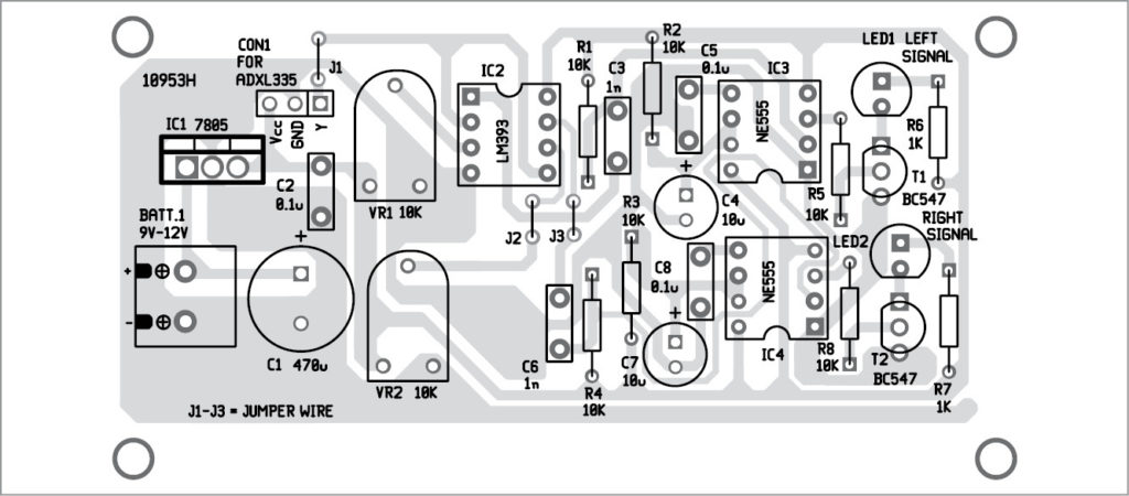
The PCB layout for the Automatic bike turn indicator is shown in Fig. 4 and its components layout in Fig. 5. Assemble the components on the PCB as per the circuit diagram.
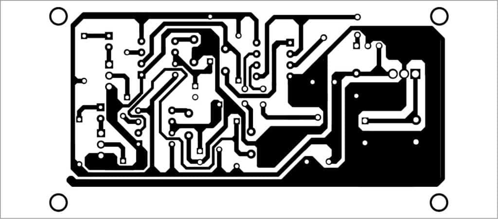
Download PCB and component layout PDFs: click here
Connect a 9V-12V power supply to the circuit. Adjust voltages at pins 3 and 6 of IC2. The bike signal turn indicator is ready for use.

do the indicator gets off automatically ?
Yes, the indicator turns off automatically when bike handle becomes straight.
Do the indicator Turns Off automatically after turning ??
The indicator will be turned off only when the bike’s handle becomes straight.
This would be great except……turn signals are supposed to be turned on BEFORE the turn (for ALL vehicles.) It does absolutely no good to turn on a turn signal when you’re already started into the turn.
Way too many people wait till they’re at a complete stop and then turn on the signal. Utterly useless. If your brake lights come on before your turn signal does, you’re doing it wrong (and illegally.)
Thanks for the feedback! Firstly, it is not a complete commercial product and so you cannot use this circuit as it is. There are some few advantages this circuit can be extended to be used in the existing turning indication system. First, if you forgot to switch on the turning indicator during turning, it will automatically turn on for you. Second, this also applies to if you are trying to change lanes. Third and important application is to switch off the indicator automatically when bike’s handle becomes straight. Switching off right/left indicator is important when not required as it can confuse/irritate the bike or vehicle around you. Sometimes accident may happen if your right indication is on and you make a left turn.
sir pls send me to bacck portion of author’s prototype.
can we run its simulation on proteus?
Can anyone explain why the author’s prototype only has 4 capacitors when the design has 8?
Is there any way to contact the author personally? I really need help.
You can send a mail to [email protected].
The force vector of a bicycle performing a turn still points straight down. Bicycles lean during turns. This would work in a car, but won’t work on a bicycle.
if someone is just overtaking handle got tilted. so thats not a good thing to be. and practically people turn up the indicator at least 5 sec before starting to take the turn. so i dont see any use
At what angle the LEDs will starts glowing plz reply