


 Gadgets like electronic toys and musical players commonly use 1.2V rechargeable batteries in capacities ranging from 200mAh to 2800mAh, which need to be charged and maintained regularly.
Here we present a simple and low-cost device that can charge or discharge up to four 1.2V rechargeable batteries simultaneously with maximum current of around 100mA per battery. As the device uses USB power, it doesn’t require any external power supply.
Circuit and working
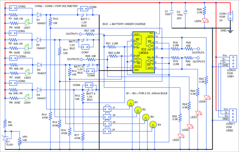
Circuit of the battery charger and discharger with USB power supply is shown in Fig. 1. It is built around four 30-ohm, 1-watt resistors (R1 through R4), four 1N4007 diodes (D1 through D4), nine LEDs (LED1 through LED9), a TL431 shunt regulator (IC1), an LM324 quadruple op-amp (IC2), four 2.5V, 200mA small bulbs and a few other components.
Battery Charger
All the four batteries (Batt.1 through Batt.4) are charged independently but simultaneously. The total charging current is below 500mA, which is the maximum current for many USB ports.
Many Ni-Cd chargers charge batteries only in series-connected pairs of two or four. The status of batteries connected in series can be different and batteries may need to be charged with different currents, up to different maximum voltages and for different time durations.
Unlike many chargers, this charger can be used to charge any number of batteries from one to four simultaneously. The charging current for all the batteries can be monitored individually with voltmeters connected in parallel across resistors R1 through R4. Connectors CON2 through CON5 serve this purpose.
The approximate charging current can be calculated as:
I = (measured voltage/30 ohms) amperes
 Here, suppose you measure voltage U1=2.7V over resistor R1, U2=3V over resistor R2, U3=2.4V over resistor R3 and U4=3V over resistor R4. With these values, you get charging currents as I1=90mA, I2=100mA, I3=80mA and I4=100mA. The charging current depends on the electric charge available in the battery. Refer the respective datasheets of batteries in order to know their charging current and the maximum allowed voltage.
The batteries can be of different types and with different initial charge because each battery is charged individually. The status of all the batteries is monitored by individual comparators in IC2 and the results displayed individually by LED5 through LED8.
Using preset VR1, you can set the reference voltage of all the four comparators to an appropriate level, say, 1.5V. The maximum reference voltage (2.5V) is set by IC1. Comparator A4 of IC2 monitors Batt.1, A3 monitors Batt.2, A2 monitors Batt.3 and A1 monitors Batt.4. So, for example, if the voltage of Batt.1 is higher than the preset voltage, LED8 will glow.
Battery Discharger
Sometimes you need to manually discharge the rechargeable batteries. That can be done easily with this circuit. First, remove the power supply from the circuit. Next, close the respective jumpers. For example, if you wish to discharge Batt.1 and Batt.2, close only J1 and J2. The batteries start discharging through electric bulbs B1 and B2. You may connect voltmeters across CON6 and CON7 to check the voltage status on the corresponding discharging batteries.
To drain the batteries, choose bulbs with appropriate ratings. In most cases, bulbs rated 2.5V/200mA or 2.5V/300mA will do the job. You may also use 3.5V/300mA or 6.3V/300mA bulbs but these produce dim light. Open the jumpers J1 through J4 when you charge the batteries.
This battery charger does not need any special adjustment to operate properly. You only need to set the comparator threshold at 1.5V or any other appropriate power supply. Equalisation resistors R1 through R4 are around 30-ohm, but you can choose any appropriate value. You can also remove R1 through R4, if desired. Resistors R5 through R8 protect LED1 through LED4. The light emitted by these LEDs is proportional to the charging current.
Construction and testing
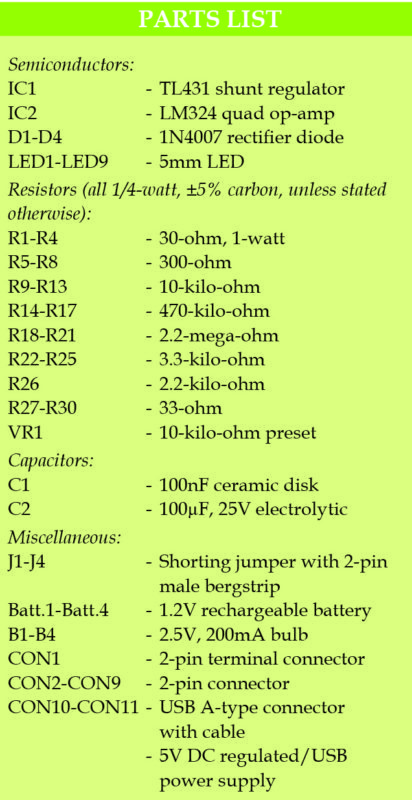
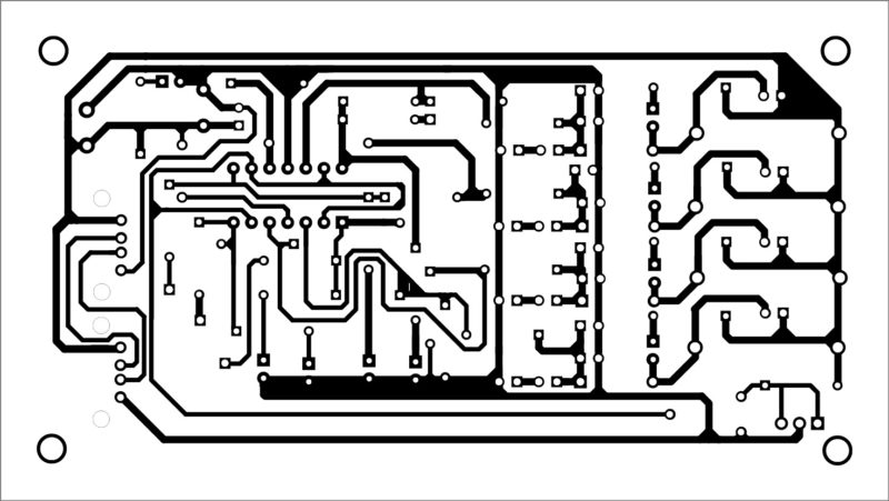
A single-side PCB layout for the battery charger/discharger with USB power supply is shown in Fig. 2 and its components layout in Fig. 3. After assembling the circuit on a PCB, connect CON1 to 5V power supply. Connect bulbs B1 through B4 on the front panel to indicate the discharging status.
Download PCB and component layout PDFs: click here
This article was first published online on 18 September 2017 and was updated on 21 April 2020.