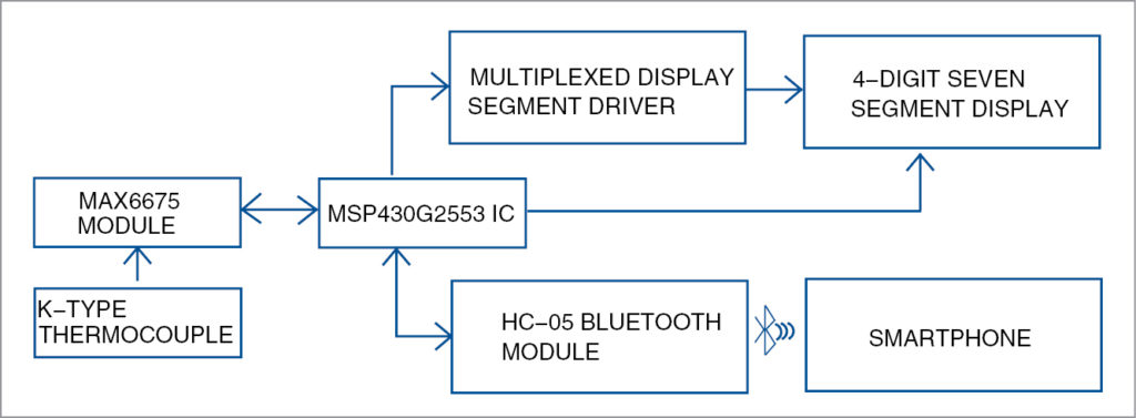
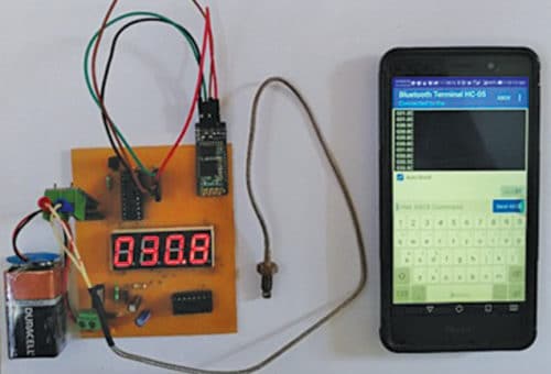
 This project presents a K-type thermocouple-based temperature measurement system using MSP430G2553 microcontroller (MCU). The MCU reads sensor data and updates it on a four-digit, seven-segment display, and also sends it to a smartphone through Bluetooth module. The author’s prototype is shown in Fig. 1 and its block diagram in Fig. 2.
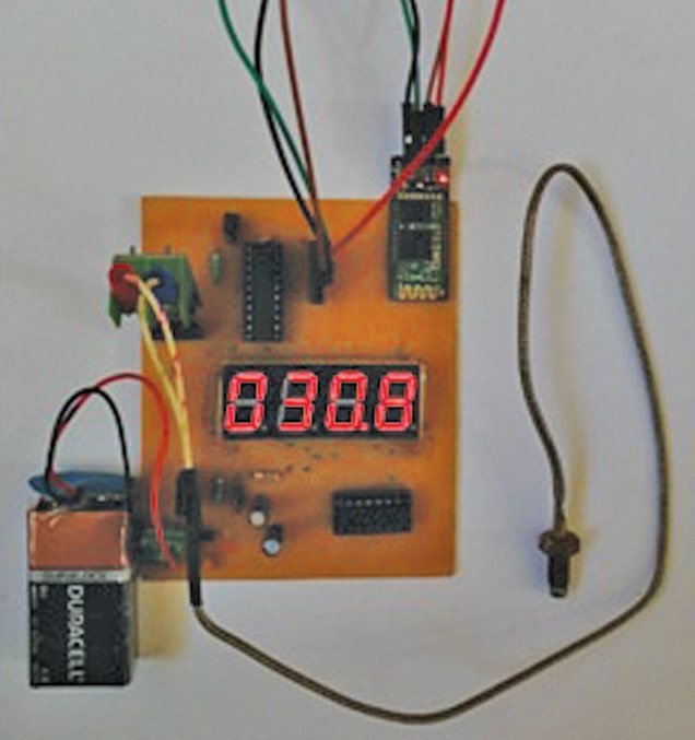
Temperature measurement is vital in various industrial and weather-monitoring applications. Resistance temperature detectors (RTDs), thermistors and thermocouples are commonly used as sensors for temperature measurement in industrial applications. K-type thermocouples are widely used in industrial applications as these work well in rugged environmental conditions and in various atmospheres. These can provide temperature measurements in the range of -270°C to 1260°C, and an output of -6.4mV to 54.9mV over maximum temperature range. Thermal response of K-type thermocouples is also fast as compared to RTDs and thermistors.
Circuit and working
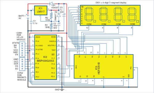
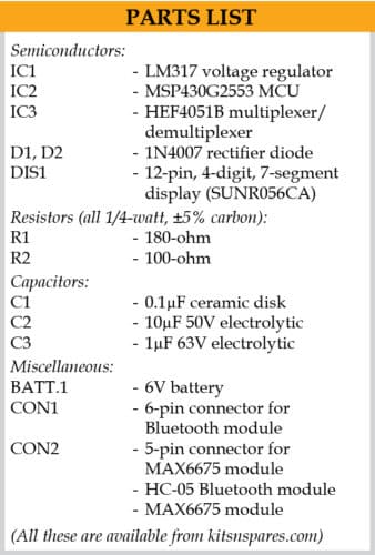
Fig. 3 shows the complete circuit diagram of the system. K-type thermocouple is used for temperature sensing and MAX6675 module is used as signal converter. MAX6675 performs cold-junction compensation and digitises the signal from K-type thermocouple. Data is output in a 12-bit resolution and communicated to the MCU through SPI protocol. MAX6675 provides a resolution of 0.25°C, and allows temperature readings from 0°C to +1024°C.

MSP430G2553 (IC2) is an ultra-low-power mixed-signal MCU with 16-bit RISC CPU, and has a digitally-controlled oscillator for data processing. A twenty-pin MSP430G2553 MCU is used here. It periodically acquires data from the signal converter and converts the digital data into corresponding temperature value.
Converted values are sent to the four-digit, seven-segment display (DIS1) through an analogue multiplexer/demultiplexer HEF4051B (IC3). Through pin P2.7 of MCU, temperature data is sent serially to pin E of HEF4051B to update the segments of the digit.
Pins P2.0, P2.1 and P2.2 of the MCU are connected to selection pins S1, S2 and S3 of HEF4051, respectively, to select the particular segment of a digit in DIS1. Pins P2.3, P2.4, P2.5 and P2.6 of the MCU are connected to pins 12, 9, 8 and 6 of DIS1, respectively, to select a particular digit.
The MCU also sends data to the smartphone through HC-05 module. HC-05 is a Bluetooth Serial Port Protocol (SPP) module interfaced with the MCU through UART. Pins RX and TX of HC-05 are connected to pins P1.1 and P1.2 of the MCU, respectively. HC-05 Bluetooth module is used to communicate between the smartphone and the circuit. A 9V PP3 battery or a suitable DC power supply adaptor is used to power up the system. LM317 is used as voltage regulator to provide 3.3V to 3.6V.
DIS1 is capable of displaying temperature up to 999.8°C. Temperature measurement can also be viewed through an Android smartphone with Bluetooth Terminal HC-05 app installed. Connect Bluetooth of the smartphone with HC-05 Bluetooth module in the circuit. Default auto-pairing password is 1234.
Next, open the app; you will notice a list of nearby Bluetooth devices. Select HC-05 from the list to connect it.
Send ST ASCII value to HC-05. Whenever UART of the MCU gets the command ST, it will send data to HC-05, as shown in Fig. 4.
Software
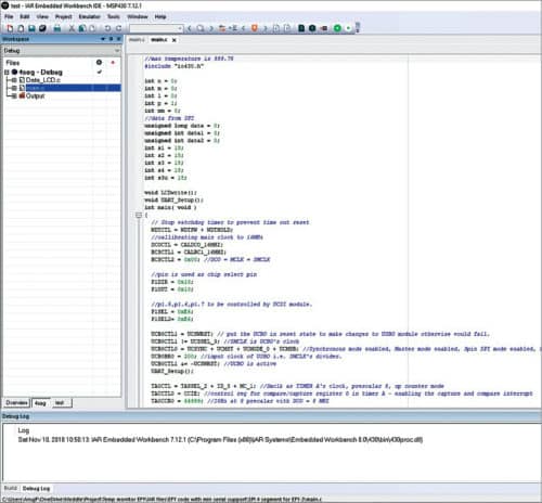
Fig. 5 shows the integrated development environment (IDE) of the IAR-embedded workbench for MSP430 version 7.12. KickStart edition is used to develop the firmware in embedded C and program MSP430G2553. MSP430 LaunchPad Kit is used to burn the program to the MCU.
The following steps are used to develop and burn the firmware to the MCU:
- Install IAR-embedded workbench for MSP430 (IAREW) on Windows PC.
- Register for KickStart (free) licence.
- Open IAR-embedded workbench IDE.
- Select File->New Workspace.
- Open Project->Create New Project->Expand C Tree Node->Main, Toolchain->MSP430. Click OK.
- Give a filename and save it.
- Copy and paste the source code (main.c) in the text editor.
- On the workspace (left pane), right-click on the project name. Select Options->Category->General Options Device->MSP430G2553.
- Select Category->Debugger->Driver->FET Debugger.
- Connect MSP430 LaunchPad Kit (with MSP430G2553) with the PC using USB type A male to USB type B mini cable.
- To burn the code to the MCU, select Project->Download->Download active application.
After burning is complete, remove the MCU and place it on the temperature measurement target board. It is always good to save the file by giving a filename and clicking on Save.
Troubleshooting
In case there is a problem in running the project, troubleshoot using the steps given below.
-
- Download and install MSPDRIVERLIB from this page.
- Select Category->FET Debugger->Connection->Elprotonic USB-FPA, Manual Selection->Spy-Bi-Wire.
The firmware performs the following functions:
- Halt watch-dog timer and initialise the internal clock to 16MHz (digital-controlled oscillator).
- Initialise USCI for SPI and UART.
- Initialise the timer to create periodic interrupts.
- For every timer interrupt, read sensor data from MAX6675 and convert that digital data to temperature.
- Update the value on seven-segment display.
- If UART receives ST in ASCII, it will keep sending temperature data to HC-05 module for every timer interrupt.
Construction and testing
While constructing the circuit, care must be taken to check all components prior to assembly. This includes checking HEF4051B by connecting digital select pins, ground pin, inhibit pin to 0V and VDD pin to 3.6V.
Now, give input to pin Z; it must be reflected at output pin Y0. If Z is high, then Y0 is high, and vice-versa. Connect inhibit pin (E) of HEF4051B to high (VDD). Output Y0 should be floating.
Test the four-digit, seven-segment display (DIS1) using a multimeter in continuity mode, and map the pins including anode and cathode. Pin details of DIS1 used in the project are shown in Fig. 6.
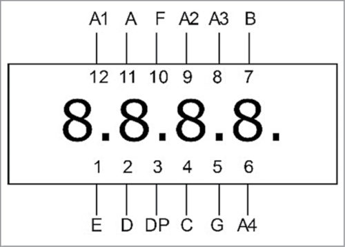
Need for the resistor to limit current to DIS1 is eliminated due to the presence of internal resistance of HEF4051B.
Whenever the Temperature Measurement System system is powered on, the MCU waits for timer interrupt (~1sec). Upon timer interrupt, the MCU starts to acquire temperature data from the thermocouple sensor through MAX6675 module and converts digital data to valid temperature data, and displays the same on the four-digit, seven-segment display (DIS1).
Download Source Folder
J. Anuj is an electronics hobbyist. His area of interest includes automotive electronics, embedded systems, artificial intelligence (AI) and Python programming
Dr K. Vairamani is assistant professor in Department of Electronics, St. Joseph’s College (Autonomous), Tiruchirappalli, Tamil Nadu. His area of interest includes instrumentation and wireless sensor networks