 Bluetooth has a max. range of 10m but this device can cover up to 1Km. You heard that right..it’s not a joke. Read the article to find out more.
Taking care of patients or elderly people at home is quite challenging, especially when you are busy at work and cannot directly contact them.
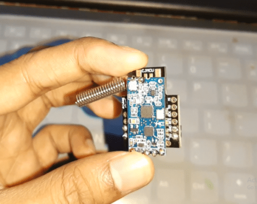
To present a unique solution to this problem, I have developed a device through which you can instantly receive notifications whenever medical patients or elderly people need help. With just a push of a button, this wearable device can also monitor their movements, besides health. If a person does not move for a long time or suddenly falls, then the device alerts the caretaker about the same.
The main challenge while working on the project was to incorporate a suitable communication protocol for the device. WiFi wasn’t convenient as its coverage is limited to only a few metres (approximately 20 metres). For long-range coverage, several WiFi modules are required to create a mesh. BLE also faces the same problem.
Since the usage of WiFi technology for most of the time is not feasible in parks and garden lawns, the developed Bluetooth-based device allows connectivity even in such environments – within a 1-kilometre range. Yes, you read that right…up to 1 KM!!
Here I have used the HC-12 Wireless Transceiver module, which works on a bandwidth of 433.4 – 473.0 MHz. Although it’s not supported by a phone’s Bluetooth frequency band, you can additionally use the HC-05 Bluetooth module to connect with your phone.
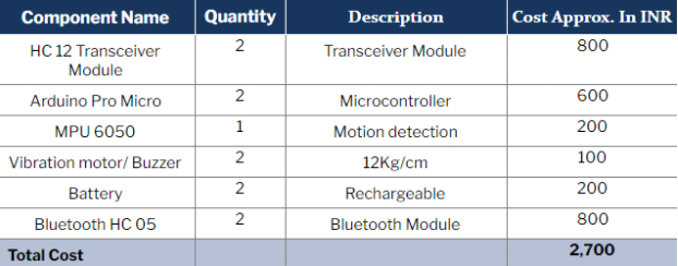
So let’s start the project by collecting the following components.
Bill of Material
Coding
We need two devices: transmitter and receiver to transmit and receive data respectively. So, assign the wearable device for patients/elderly people as a transmitter and the other device as a receiver for caretakers.
Code for Transmitter
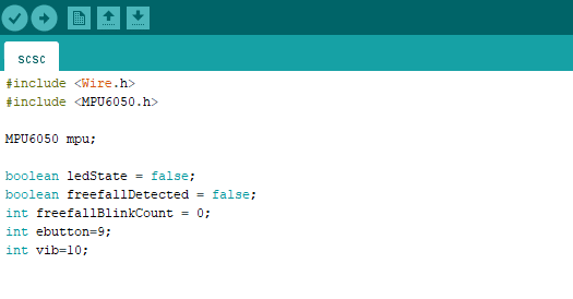
Open the Library Manager in Arduino IDE, search MPU6050 and click install.
Now include it in the code and define the pin numbers for device vibration feedback and emergency button.
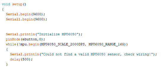
Next, create a setup function for the Arduino serial port. The Arduino Pro Micro has two USART ports: Serial and Serial1. Both are used in the code; one for communicating with the HC-12 module and the other with USB Serial Port. The default baud rate of HC-12 is 9600. Use the same baud rate for both serial ports.
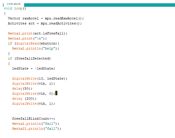
Code for Receiver
Define the pin numbers for notifications.
Next, set the serial port and baud rate for communication with Bluetooth HC-12 and HC-05 (if the device needs to be connected with a phone).
Then create a loop for checking incoming messages from the transmitter. Also, make sure to transfer them to the Bluetooth HC-05 module on software serial (if you are connected with a phone). This will allow you to see the messages in the Bluetooth terminal app.
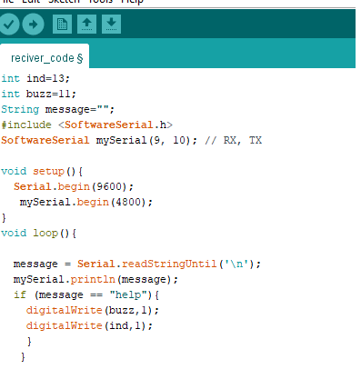
If your Arduino board does not have pin 1, then change to pin 8 for buzzer/motor vibration.
Connection
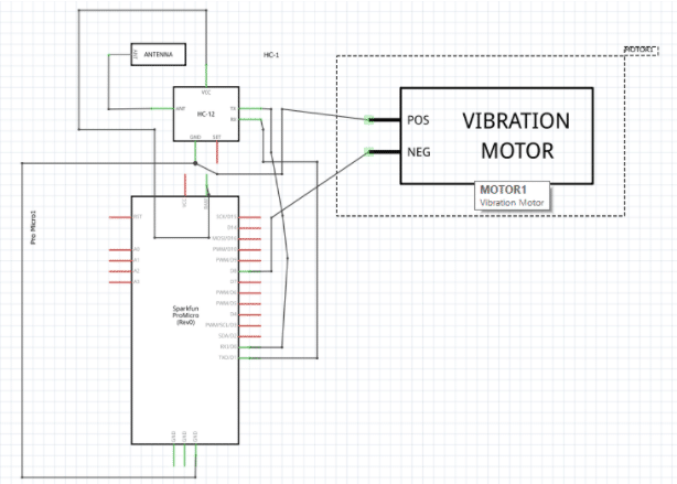
Connection for transmitter
Connect the components as shown in the circuit diagram. Then connect the 3-5V battery to the Arduino Pro Micro board. Make sure to join the positive terminal to the power pin and negative to GND.
Also refer to the separate connection diagram for MPU to better understand the connections.
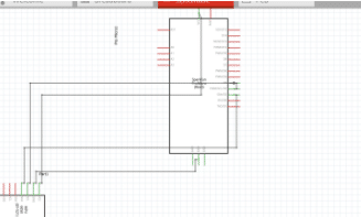
Receiver circuit diagram
Enabling range to 1KM
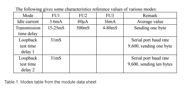
The first step to extend the range is to add an antenna. You can do so by either soldering a 433MHz spring antenna or adding an IPEX20279-001E-03 antenna socket. The module works in different modes and has different ranges in each of them (refer Table 1).
As you can observe, long-range can be achieved only in the FU3 mode. To set the FU3 Mode, use the AT command. But first, set the module in command mode.
To do that, set the SET pin to LOW by connecting it to GND. Then open the serial terminal and type AT. If it responds with an “OK” message, then this means that you are now in AT mode. After that, send AT+FUx for changing the mode. Here, x denotes the mode number you want. Since the 3rd mode is to be used, so type AT+FU3.
Next, set the transmission power to 8 by typing AT+P5. The transmission power ranges from 1 to 8 where 8 is the maximum transmission power, suitable for long-distance transmission. 1 stands for the lowest transmission power.
Testing
To test the device, try falling. It will detect that action and notify the other person through vibration. Also, press the button on the device to check whether it notifies the other connected device. Note that the transmission range may differ according to the environment, and the area density range might be more or less than 1 kilometre.
Congrats!! You have made the Bluetooth-based long-range patient assistance device.


Hello! I’m interested about your about and we’ve decided to make this as our robotics project in our school. However, I’m still confused about the diagram in the Transmitter connection. Can I have a request to send me a clearer pic of this. Thank you very much! I hope you will notice this it will be a big help for us.
You can contact me on what’s app 7061350809 for more help needed
Thank you very much sir! Sorry for the late response