


Learn how these systems monitor, manage, and control critical aspects of vehicle performance, safety, and efficiency, leading to a cleaner, more sustainable transportation future.
Battery Management Systems (BMS) and Vehicle Control Units (VCU) play pivotal roles in the modern automotive industry, driving advancements in electric vehicles (EVs) and hybrid electric vehicles (HEVs). A BMS is crucial for monitoring and managing the battery pack’s performance, health, and safety, ensuring optimal operation and longevity. On the other hand, a VCU acts as the vehicle’s brain, controlling various systems, such as the powertrain, braking, and steering, to enhance performance, efficiency, and safety. Together, these systems enable the transition to cleaner, more sustainable transportation options, making them essential components in developing next-generation vehicles.
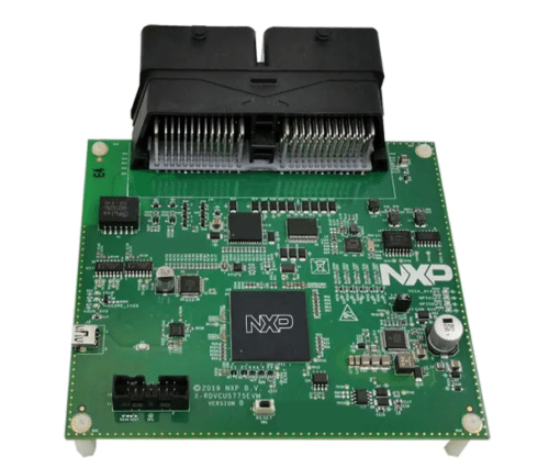
The RDVCU5775EVM by NXP Semiconductor is a comprehensive reference design tailored for ISO 26262 ASIL D automotive applications, seamlessly integrating the functionalities of both a battery management system (BMS) and a vehicle control unit (VCU). This ready-to-use solution is designed to streamline the integration of high-voltage components, offering a cost-effective and proven-concept approach. Its core features key elements such as the 32-bit Power Architecture MPC5775B MCU, the FS6523 functional safety power SBC, and the MC33664 high-speed transceiver physical layer (TPL) network. This robust design supports advanced features such as the MC3377x battery cell controller EVB daisy chain and the CD1030 33-channel multiple switch detection interface (MSDI) with programmable current, ensuring compatibility with various automotive applications.
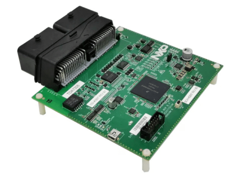
It includes integrating BMS and VCU functionalities into a single ECU, support for dual TPL communication with a daisy-chain of BCC devices, and multiple input/output interfaces, including MSDI, ADC, GPIO, LSD, and HSD. It also offers a variety of communication interfaces such as Ethernet, CAN(FD), LIN, and UART, along with two demo app projects for S32SDK and AUTOSAR MCAL, a GUI tool for easy system monitoring over CAN, and a bootloader based on UDS on CAN protocol. In terms of hardware specifications, it has an MPC5775B microcontroller (416 MAPBGA soldered), MC33FS6523CAE system basis chip (SBC) for board power supply and one CAN physical layer, and MC33664 isolation transceiver supporting a daisy chain of BCC device MC33771 communication. It also includes a 100BASE-T1 Automotive Ethernet interface TJA1101, three CAN interfaces (two supported via TJA1052 and TJA1145 CAN FD transceivers, another via SBC), one LIN interface MC33662BLEF, a PCA85063A automotive tiny Real-Time Clock/calendar with alarm function and I²C-bus, a 1 Mbit automotive external EEPROM with SPI interface, and a standard 14-pin JTAG debug connector. The design requires a 12 V external DC power supply and includes main power regulator status LEDs plus two user LEDs connected to GPIO for testing purposes.
This reference design from NXP Semiconductor has undergone comprehensive testing and includes a Design Guide, Bill of Materials (BOM), schematics, Gerber files, Printed Circuit Board (PCB) layout, and additional resources. Please visit the company’s website for further information on this reference design. To delve deeper into this design, click here.
