


 You may already have on hand a 12V AC/DC adaptor or 12V from your PC or 12V battery, but you need a 9V, 2.5A DC power supply for your embedded system. Certainly, you will need a DC-to-DC converter for the same. You can use a linear regulator but that requires a large heat-sink. Here is a better solution to convert 12V DC to 9V DC using a five-lead TO-220 package IC LM2576.
Circuit and working
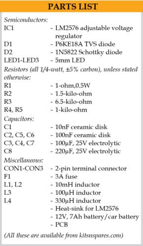
Fig. 1 shows the circuit diagram of the 12V DC to 9V DC converter with input filter and protection. It is built around adjustable voltage regulator LM2576 (IC1), two diodes P6KE18A and 1N5822 (D1 and D2), and a few other components.
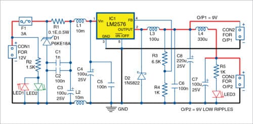
Input voltage can be regulated or unregulated. LED1 indicates reverse polarity, and LED2 indicates the presence of input voltage. F1 is a resettable fuse, selectable according to current capabilities of voltage source and D1 is transient-voltage-suppression (TVS) diode, also known as transil.

Transil is selected according to maximum input voltage. It can be omitted or replaced with a diode having forward current above 5A. Transil can also be unidirectional or bidirectional depending on requirement, to protect the circuit from reverse input voltage.
Resistor R1 is used to monitor input current of the circuit. Capacitors C1, C2 and C3 are input composite capacitors for filtering input noise and ripples. L1 and L2 are inductors wound over the same common core, and are used to protect input of the IC from input ripples and noise.

Inductors are selected according to maximum output current. There is a large variety of inductors available. You can use inductors from old TV sets, monitors or other electronic equipment. You can also use two separate inductors (L1 and L2), but that will give lower filtering capabilities. Capacitors C4 and C5 provide the required filtering and reservoir capabilities for the IC.
LM2576 is adjustable, and its output voltage can be varied from 1.23V to 37V. Here, you need input voltage slightly higher than 9V. External shut-down capabilities of the IC are not used. Switching frequency of the regulator is around 52kHz, higher than the audible frequency range.
D2 must be a Schottky diode (for example, 1N5822, MBR360, MBR340, SR304 or equivalent) with maximum DC current above 3A. L3 is the only obligatory inductor in the circuit.
Parameters of L3 depend on the required maximum output current. Selection of appropriate inductor values for L3 along with examples can be found in the datasheet of LM2576.
Output voltage is programmed with resistors R3 and R4. Output voltage Vout can be calculated using the following relationship:
Vout=1.23V×(1+R3/R4)
Also, if you know Vout and R4, you can calculate R3 easily using the following relationship:
R3=R4×(Vout/1.23V–1)
Internal reference voltage of LM2576 is 1.23V. Voltage produced by L3 is filtered with at least two capacitors—an electrolytic capacitor (C8) and a high frequency capacitor (C6).
Additionally, output is filtered with LC filter built around L4 and C7. Glowing of LED3 shows the presence of output voltage. The circuit was designed for output current of 2.5A but output current can reach 3A and, in that case, output voltage will drop by around 0.3V.
Construction and testing
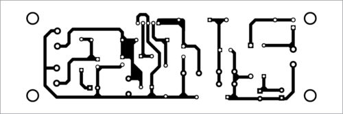
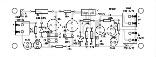
An actual-size PCB layout for the 12V DC to 9V DC converter is shown in Fig. 2 and its components layout in Fig. 3. After assembling the circuit on the PCB or veroboard, enclose it in a suitable cabinet. Fix LED1 through LED3 on the front panel, and CON2 through CON3 on the rear side of the panel for outputs.
For downloading PCB and component layout PDFs: click here
Heat-sink for LM2576 depends on input voltage and load current. Power dissipation on LM2576 can be significant and, hence, requires a small heat-sink with thermal resistance lower than 30°C/W.
Output voltage (9V, 3A) is available across connector CON2. Low-ripples 9V output voltage can be obtained at CON3. Input voltage from 11V to 15V can be connected at CON1. Maximum input voltage is limited by maximum voltage of input capacitors and maximum power dissipation of the IC.
The circuit can be connected to the electrical installation of your car, but make sure that input is within the working range (11V to 15V). Care should be taken because if the engine is running and you disconnect the 12V battery of the car, or if the voltage regulator in the car is not working properly, voltage generated from the generator could be much more than 40V and pulses may go up to around 100V.
Also, transitions can generate negative input voltages. In real applications, input filtering capacitors should have working voltages of 150V. It is suggested to have a set of electrolytic and ceramic capacitors covering large frequency ranges.
Petre Tzv. Petrov was a researcher and assistant professor in Technical University of Sofia, Bulgaria and expert-lecturer in OFPPT (Casablanca), Kingdom of Morocco. Now, he is working as an electronics engineer in the private sector in Bulgaria

Sir, the capacitor C1 value in Circuit diagram and Components layout for the PCB are denoted as 1nF. But in the parts list the value of C1 is denoted as 10nF. What capacitor value I should use for C1? Which one is correct?
C1 should be 1nF.
Thanks for pointing it .