


Building a Manufacturing Test for the system which ensures quality and performance of the system is very critical and the pivotal task for every product manufacturer. In case of bulk manufacturing, the test strategies and component coverages are very important to ensure adherence to industry standards as well as delivery of good quality products to the customers.
Today’s manufacturing tests involve very complex strategies managing multiple devices in parallel. Design of an effective test equipment is cardinal in terms of ensuring the system to be uniform in quality and robust, rugged and highly reliable with respect to frequent use in lifespan or serviceability of the product. Adjunct requirement is to provide uninterrupted service, which ensures any undesired interruption in manufacturing process. While in operation in field, the manufacturing test equipment requires timely re-checking and re-validation to ensure quality, reliability and performance meet specified standards and if not, the equipment are needed be repaired or replaced with a qualified one.
Before shipping a product, it undergoes numerous testing process to verify its intended functionalities. Each printed circuit board assembled with components undergoes physical examinations (AOI or Flying Probe Test) to ensure assembly of correct components in correct orientation. Following the board level diagnostics and test routines, the qualified units are tested for hardware functionality and system level integration. There are various test strategies to be considered for these.

In Circuit Test (ICT) performs electrical probe tests on an assembled printed circuit board (PCB). In this manner electrical signals are directly applied to the on-board components or device terminals and the output responses are recorded. Generally, ICT is performed to find electrical shorts between device terminals, continuity between nodes, incorrect assembly, power supply and device functionalities using JTAG/boundary scan technology etc. The units are tested on bed of nails with spring loaded pogo-pins making contact with numerous test points on the PCBs. In Circuit Test methodology is a very powerful tool, however it has some limitations. It cannot test the quality of electrical contacts and if multiple components are assembled in parallel, it cannot determine individual failures. Actually in circuit testing is not meant to verify critical circuit parameters and functions.
Functional testing analyzes the PCBs as a complete circuitry or system. The units are simulated by providing signals though connectors and the outputs are recorded. The operator or an automatic tool analyzes the responses and determine whether the circuit is working properly or not. The test also covers regression test, integration test. Functional testing usually verifies what the systems are intended to do.
Functional testing differs from system testing in that functional testing “verifies a program by checking it against … design document(s) or specification(s)”, while system testing “validate[s] a program by checking it against the published user or system requirements” (Kaner, Falk, Nguyen 1999, p. 52).
In circuit test and functional test both cover the testing of the entire assembly in the system; but the complexity of the system determine which approach should be followed. The test development engineer should determine whether one of them is sufficient to the test the hardware.
Adjunct to in circuit test or functional test several few other test like burn in test, HAST are sometimes carried on the system hardware to determine the system quality and reliability over a specified life span. In case of Burn-in test the components and devices are electrically stressed at an increased temperature to determine the infant mortality of the system. HAST (Highly Accelerated Test, referred to as “shake and bake test” determine the robustness of the system against elevated temperature and vibration conditions. However, these tests are performed on a sacrificial board in order to collect information about the reliability and expected product life.
Developing a test strategy should be done in parallel with system design, because design should be done considering the testability (Design for Test). In the process of developing the manufacturing test methodology one should consider the suggestions from board fabricator, assembly process engineer, system design engineer as well hardware board designer. The review team consisting each one of them at minimum should consider the test coverage, the testing concepts and that should economically facilitate the fault detection during manufacturing. At the design phase, the manufacturing test development engineer should work closely with hardware board designer and suggest changes to improve the testability of the system. On the other hand, any changes done in the system that impact the test program should be apprised to the test engineer to determine the best compromise.
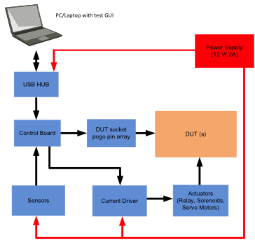
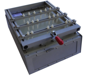
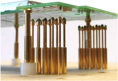
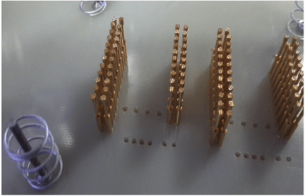
As discussed earlier, traditional manufacturing test fixtures have a bed of nails inserted into holes in an epoxy phenolic glass cloth laminated sheet (G-10). The bed of nails consists of an array of small, spring-loaded pogo pins which are aligned such as to make contact with test points or GPIOs on a printed circuit board and are also connected to a controller board using wires. Sensors are placed on the top and/or back panel. The top panel locks into the bottom panel using adequate mechanism to align the sensors to components on PCBAs. The top sensor panel shall be customizable either with a linear displacement option or modular (pluggable model) to cater different component arrangement/placement across PCBAs. This bottom panel can be modified for each board depending on the number of test points and PCB dimension. The units are placed against the bed of nails and pressed downwards manually or by means of vacuum. All the key hardware components are then tested manually with human intervention or using an automated tool.
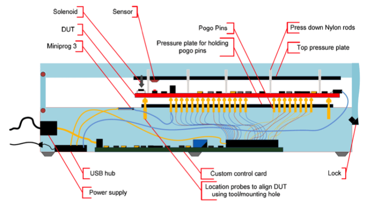
The spring loaded test probes used for implementing bed of nails are chosen with proper tip styles, plating, spring forces as per requirement. The internal spring exerting force on the probe tip should be selected depending on the surface finish of the test target or else the higher spring force damage the components on board. Serrated, Cup shaped or crown shaped probe tips are used normally to test component leads. To test terminal points, slotted cup or flat shaped probe tips can be used. Spear, sharp chisel or needle shaped probe tips are recommended to use for testing pads which ensures increased tip contact pressure for reliable testing. To test plated through holes or vias, chisel or arrow head probe tips and for solder beads/bumps/domes micro-serrated probe tips can be used.
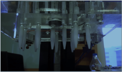
Different tests ranging from voltage range measurements, LED color and intensity measurements, Capacitive touch functionality, audio testing, USB and other serial port functionality and RF measurements are done inside the test fixture. In case automated manufacturing tests, apposite sensors are used to validate the components on board, like color sensor for RGB LED and electromechanical units like solenoids, relays, servo motors and actuators to activate or test switches. Compared to manual and semi-automatic methods, automated test methodologies are less susceptible to any false pass or miss (caused mainly due to human error) during testing. Although automated manufacturing test facilities are pretty expensive, industries prefer to go for them as they can improve the testing time and coverage for each product considerably.
Today’s manufacturing tests incorporate high level of complexity managing multiple device firmware in multiple PCB boards. In adhere to that, the test programs are frequently being ameliorated to comply with production changes or to fix bugs in firmware. The task of managing the variability and changes in manufacturing test process is arduous and fallible in particular when testing and production are done off-site. Proper change management system and version control tool obviates any fault or issues which might impede the manufacturing process.
With the advancement of electronic industries, products are becoming smaller with increased functionalities and the requirement for testing each and every part of the system are becoming very critical. Traditional methods require enough room to place probes and seemingly appear very difficult in case of designs with fine pitch parts, particularly with embedded components. The paucity of proper testing tool and mechanism has led the industry to seek for new techniques and alternate method of testing.
