


Visual display technology leaps forward with an innovative driver chip, energizing 16×16 LED matrices for rich, detailed, and dynamic visual communication.
The rise of LED technologies has ushered in a new era for display and lighting solutions, bringing efficiency and a broad spectrum of design possibilities. Key to harnessing the full potential of LED arrays is sophisticated driver chips, which streamline the process of controlling these lights, allowing for intricate and customizable displays. While the industry standard has often been confined to smaller 8×8 LED matrices, this approach has its limitations, particularly in the realm of expressive and sizable character displays, as well as in maximizing the chaining capabilities that modern driver chips offer.
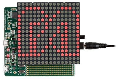
Moving beyond this limitation, developing a driver for a 16×16 LED matrix marks a leap forward. This advancement paves the way for more complex and informative displays that present a wide array of international symbols and alphanumeric characters, particularly useful in global communication applications. The reference design MAXREFDES99 launched by Analog Devices emerged as a significant development, driving a 16×16 display and thus becoming an invaluable asset for prototyping and application development.

Compatible with mbed and Arduino, the design facilitates rapid development across these platforms. It boasts a shield with four interconnected MAX7219 chips, which collectively control four 8×8 red LED dot-matrix displays. These are configured in an arrangement to create a larger 16×16 matrix display.
The reference design requires a dedicated external power supply, commonly known as a wall-wart, capable of delivering at least 7 watts (W) and an output voltage between 7.5 volts direct current (VDC) and 12VDC. This power is sufficient for the display and the accompanying microcontroller platform via the VIN pin. For coding and development purposes, it’s possible to use a USB port for power, but caution is advised to avoid surpassing the 5V rail’s power limits of the user’s platform. The optimal power setup for the MAXREFDES99 is through a wall wart plugged into the J1 connector.
For compatibility with 3.3V platforms, the design incorporates the MAX3390E level translator, ensuring that the interface with the MAX7219 display drivers operates at the correct logic level. Communication with the display is facilitated through a serial interface utilizing pins D10, D11, and D13 for LOAD, DIN (Data In), and CLK (Clock) signals, respectively. The four MAX7219 drivers are arranged in a daisy-chain configuration, with the DIN of each subsequent driver connected to the DOUT (Data Out) of the previous one. The DOUT of the final driver in the sequence is not utilized.
Analog Devices has tested this reference design. It comes with a Bill of Materials (BOM), schematics, Printed Circuit Board (PCB) layout, etc. You can find additional data about the reference design on the company’s website. To read more about this reference design, click here.
