


 A security system having a single laser beam may not be very effective as any moving object or animal can interrupt it, causing a false alarm. Presented here is a laser security system having two laser beams with calling alert feature, using a basic mobile phone (old model), also known as feature phone.
The security system can be used in a restricted area like a farm or as a home security system. When an intruder cuts or interrupts both laser beams at the same time, an alarm sound is generated, and an alert call is made to your current mobile phone.

Circuit and Working
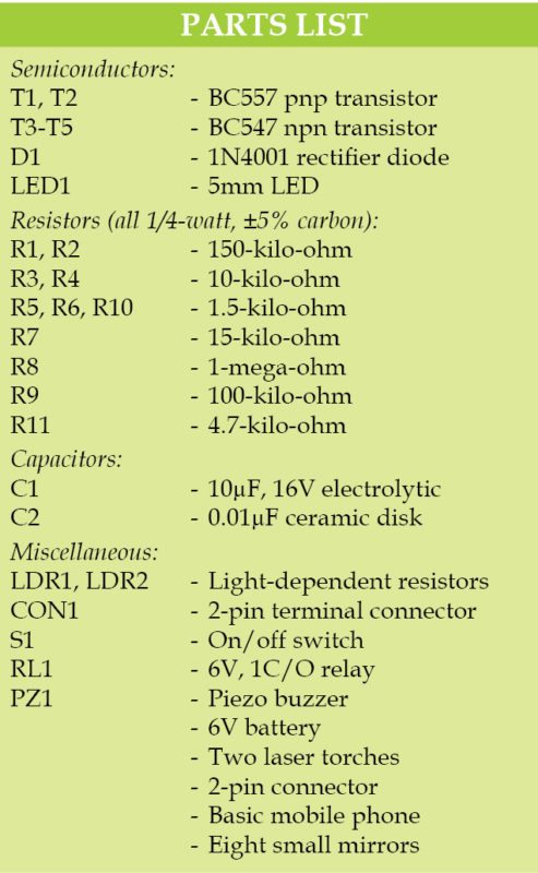
Circuit diagram of the laser security system using a basic feature phone is shown in Fig. 1. It is built around two light-dependent resistors (LDR1 and LDR2), five transistors (T1 through T5), one diode (D1), one NE555 timer (IC1) and a few other components.
T3 and T4 are configured as NAND gate. NE555 is configured in monostable mode. T5 is used to drive relay RL1 and piezo buzzer PZ1. Relay contacts are connected to the old basic feature phone through connector CON2.

When two laser beams falling on LDR1 and LDR2 are interrupted at the same time, T1 and T2 conduct, making T3 and T4 also to conduct. Output signal at collector of T3 is given to trigger pin 2 of IC1 through toggle switch S1. As a result, LED1 goes off and T5 conducts.
PZ1 sounds for a pre-fixed time based on the values of resistor R8 and capacitor C1. At the same time, RL1 gets energised and activates the speed dial function of the feature phone through CON2. The speed dial function is assigned with a specific contact number like your current mobile phone number. You thus get an alert through an incoming call on your phone.
Construction and testing the laser security system
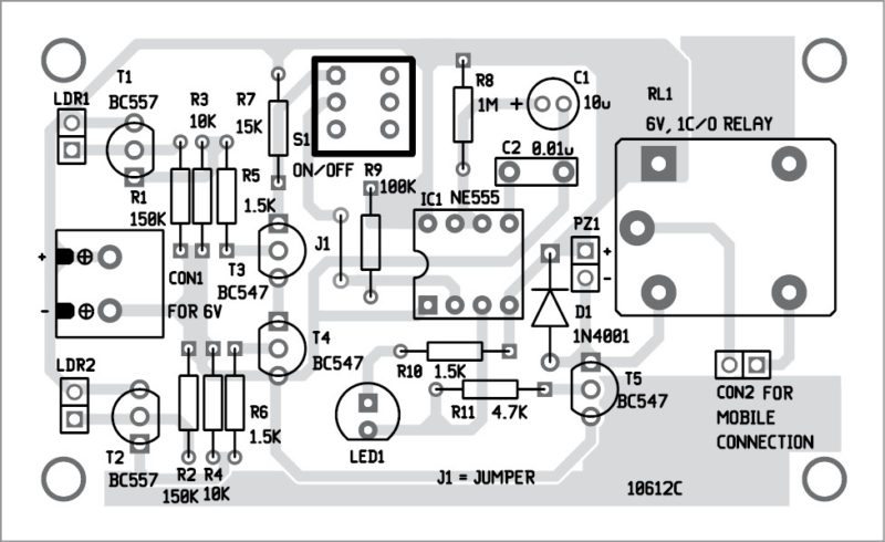
An actual-size, single-side PCB for the laser security system is shown in Fig. 2 and its component layout in Fig. 3. After assembling the circuit on a PCB, enclose it in a suitable box.
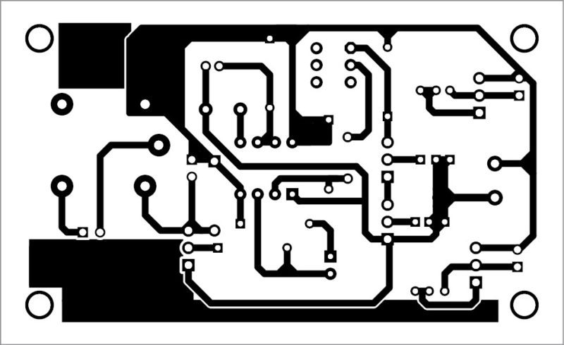
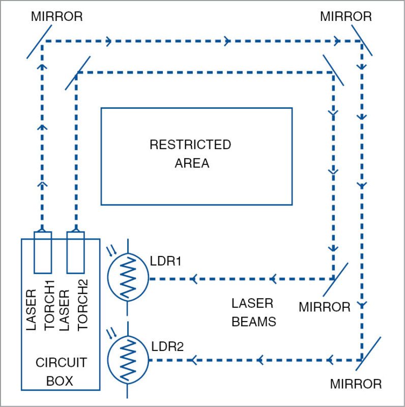
The circuit works off a 6V battery or power supply. Refer Fig. 4 for the proposed installation of laser beams and mirrors for the security system.
Download PCB and Component layout PDFs: Click here
Switch S1 to off position during installation of the laser beams and LDRs.
The project requires two mobile phones—one old basic feature phone, which will be connected to the circuit, and the other could be the mobile phone you may already be using.
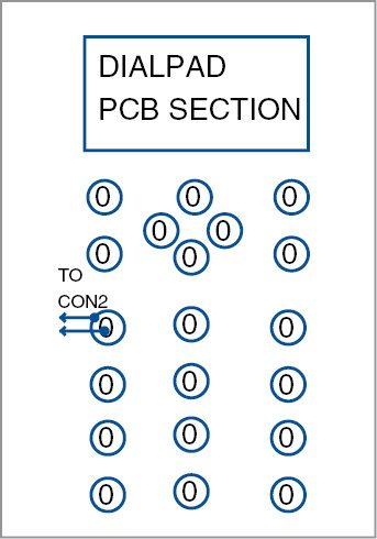
Normally, button 1 on a feature phone is assigned for speed dial function. Open the cover of the dial pad of this feature phone. Solder two wires on the PCB at 1 (Fig. 5). Extend these wires to CON2 in the circuit.
You can install the two laser beams at a slight distance from each other, depending on what you want to guard against. For example, to guard your farm against cattle, keep the two laser beams about 90cm apart, so that the animal interrupts both the laser beams when it crosses the gate of your farm.
As soon as animal enters your farm, this system will alert you, and you can take instant action. With the two laser beams kept 90cm apart, a human being crossing the gate of your farm will not produce an alarm or send an alert to your mobile phone, thus preventing a false alarm.
Pranav Rameshji Rokde and Monesh Rajendraji Wani are electronics hobbyists


hi,
I am using 5v power supply. hope this is fine for a smooth operation.
when i turned on, the ic555 is heating too much, please advise.
Can you explain better on the feature phone to be connected to relay, is it a whole phone or module or is it like please
Old feature phone like phone Nokia 1600 mobile phone was used during testing. But any GSM phone with PCB dial pad will work with this project. You need a complete phone in working condition.
Plz make a video on it. Fast. I have science project and deadline is coming fast. Plz help me.
The circuit is not working. Such circuits being certified by efy questions the credibility of the magazine