 e-ink displays are quite impressive as they use electrically activated ink molecules, which doesn’t lead to fading away of designs made using it – even after the power supply is turned OFF; the designs seem to be printed on paper with a normal ink pen. Unlike conventional display systems, e-ink does not use any LED or OLED light. It only needs a small amount of electricity.
In this IoT project, you will learn to make a power-efficient IoT touch switch that consumes minimum power and gives an impressive smart home switching experience. So let’s begin our project by shopping for the following components.


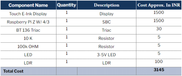
Bill Of Material
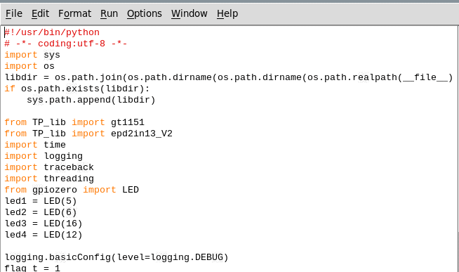
Coding
Install the latest Raspbian OS on the Raspberry Pi board. Also, install the required libraries for controlling the GPIO and for interfacing the e-ink display. For these, open the Linux terminal and run the following commands:
sudo pip3 install gpiozero

wget http://www.airspayce.com/mikem/bcm2835/bcm2835-1.68.tar.gz

tar zxvf bcm2835-1.68.tar.gz

cd bcm2835-1.68/

sudo ./configure && sudo make && sudo make check && sudo make install

sudo apt-get install wiringpi

sudo apt-get update

sudo apt-get install python3-pip

sudo apt-get install python3-pil

sudo apt-get install python3-numpy

sudo pip3 install RPi.GPIO

sudo pip3 install spidev

cd ~

git clone https://github.com/waveshare/Touch_e-Paper_HAT
Now you are ready to write the code.
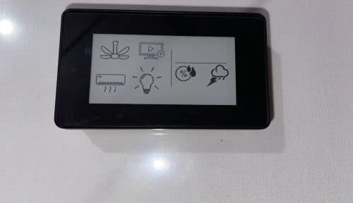
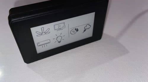
First, create a UI having the image/icon of the appliance you wish to control. Save it on the e-ink display and run the code to preview it on the e-ink display. The code can be found inside the e-ink library folder.
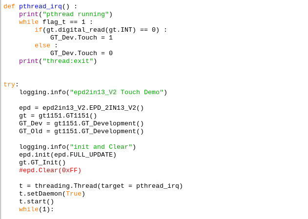
After displaying the UI, turn off the Rpi and code. As you are aware, the display will remain unchanged with the same image even after the power is switched off unless the display is refreshed. e-ink display uses a special technology of ink molecules that get activated electrically and remain on display as printed ink on paper.
Next, create a code that will check the touch/sensing points on the touch panel of the e-ink display for turning them ON/OFF as required. Import the code to the display.
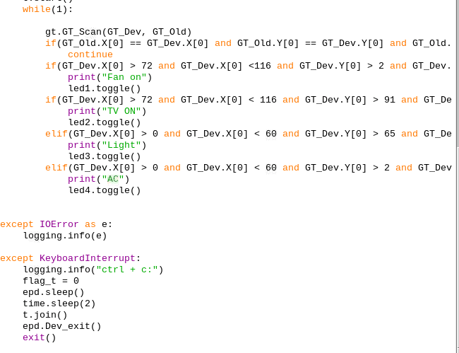
Next, create a while loop in which you should define the function for toggling the LED to control the appliance that you wish to control. If the touch/sensing point is within the range of the image/icon on display, then the LED to control that appliance will toggle.
Connection
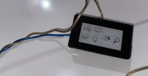
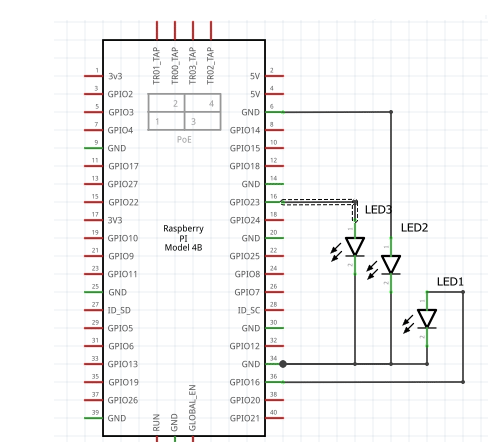
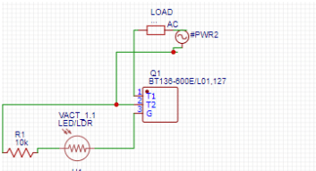
After creating the code, connect the LEDs on the Raspberry Pi pins as shown in the circuit diagram. Then make a solid state relay using TRIAC to control the AC appliance.
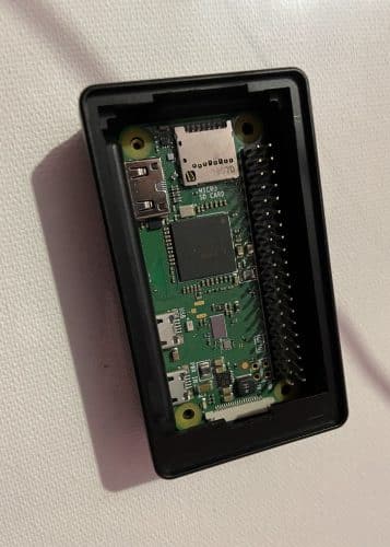
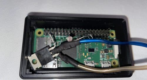
Next, assemble everything within the physical enclosure of the touch e-ink display. Put the e-ink touch display on the Raspberry Pi GPIO and connect each other on the top of the e-ink display box (refer to pics below).


Testing
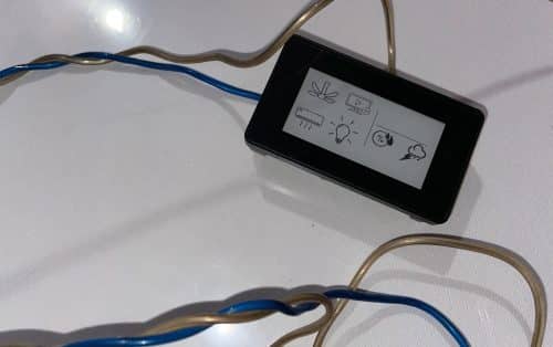
Connect the Raspberry Pi with a 5V power supply. Then plug the relay with an AC socket appliance, run the code and then touch the relevant icon on the e-ink IoT touch switch to control it.