


Stay tuned for the next exciting chapter in our journey towards design excellence! As you continue through this series, axiomatic design would inspire you to think differently about product development.
So far, we’ve discussed many important ideas, such as gathering customer and stakeholder needs, analysing risks and costs, and working on the product’s appearance. You might be wondering how to take all this information and actually create a product. In this article, we will explore the design thinking process and a helpful tool to turn that information into a well-developed design.
Galileo said in his well-known book, “Once you find them, all truths are easy to understand; the real challenge lies in the process of discovering them.” In simpler terms, product designing is like turning different needs into a clear idea that everyone can easily grasp once it’s brought to life.
Axiomatic design is a helpful tool for designing things. The name comes from the Greek word ‘axíōma,’ which means something worthy, fit, or evident. In this process, the design is based on what the customer needs. Axiomatic Design has two key rules:
- Independence. Corresponding elements from domain to domain should be independent.
- Information axiom. If two systems are otherwise functionally equal, the system that contains the least amount of information is superior.
In the axiomatic design process, we use a method similar to the QFD analysis we discussed earlier. There are four different domains involved:
- Customer domain. This is where we focus on understanding the needs and requirements of the customers.
- Functional domain. Here, we work on defining the functions or tasks that our product or system should perform to meet the customer’s needs.
- Physical domain. This domain deals with the physical elements and components that will be used to realise the functions identified in the functional domain.
- Process domain. In this domain, we consider the processes and methods needed to create and manufacture the product or system.
These domains help us systematically design and develop products that align with customer needs and perform well. (See Fig. 1 for a visual representation.)
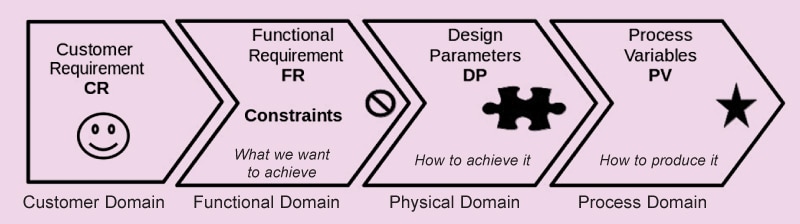
In the customer domain, we collect all the things the product needs to do for the customers. In the functional domain, we check if these ideas are practical. We consider technical and economic limitations and determine what we want to achieve. Then, in the physical design domain, we figure out how to fit all the parts together to make it work as planned. Once we have the design set, we move on to the process domain, where we think about how to actually make the product.
| Table 1: Characteristics of the four domains | ||||
| Characteristics | Domains | |||
| Customer (CR) | Functional (FR) | Physical (DP) | Process (PV) | |
| Manufacturing | Attributes that customers desire | Functional requirements specified for the product | Physical variables which can satisfy the functional requirements | Process variables that can control design parameters |
| Materials | Desired performance | Required properties | Micro-structure | Process |
| Software | Attributes desired in the software | Output | Input variables and algorithm | Sub-routines |
| Organisation | Customer satisfaction | Functions of the organisaton | Programs or office | People and other resources that can support the programs |
| Systems | Attributes desired of the overall system | Functional requirement of the system | Machines, components, or sub-components | Resources (human, financial, materials, etc) |
| Business | ROI | Business goals | Business structures | Human and financial resources |
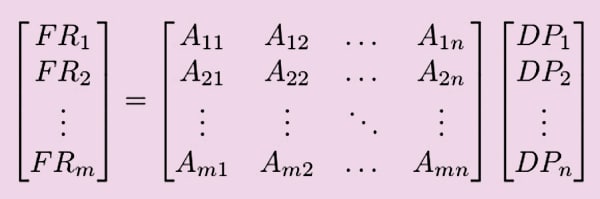
The axiomatic design uses information from QFD and applies two rules to make the design simpler and easier to control. We can represent this relationship as a design matrix ([DM]) and then map the properties as:
FR=[DM]×DP and
DP=[DM]×PV
The independence rule is met in two ways based on the DM matrix:
- Diagonal. This happens when there is a direct relationship between DP-FR or PV-DP. In this case, we can fulfil each FR (functional requirement) using an independent DP (design parameter), or a DP along with PV (process variable).
- Triangular. The DM matrix being triangular allows us to define each relation independently by following a specific sequence.
Sometimes, you might have to change the order of elements in the DM (design matrix) to make a diagonal or triangular matrix. It’s possible that the matrix has both triangular and diagonal parts. When that happens, you can divide the design matrix into sections and handle them independently.
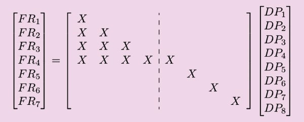
When we organise the design matrix in the way mentioned above, it is called ‘uncoupled.’ However, if we can’t arrange the relationship in a diagonal or triangular matrix, the design is called ‘coupled.’ Dealing with coupled designs is challenging. They can be really frustrating for user interfaces and, in the worst scenario, can result in products that are unusable.
Let me show you some simple examples of coupled design to explain its issues. We all know about car controls. When the driver wants to go faster, he needs to send more fuel into the engine. But, to ensure the fuel burns completely, the fuel injection time and ignition also have to be adjusted simultaneously.
Picture how challenging driving could be if, whenever the driver wanted to change the speed, they had to fiddle with two separate controls for fuel flow and ignition timing. Thankfully, in older cars, this double control was managed by the carburettor and distributor. Nowadays, modern cars have an onboard computer that handles the fuel and ignition automatically, so the driver doesn’t need to worry about those specific controls. All they have to do is press the accelerator to speed up or slow down the car. It’s much simpler and easier for the driver!
In the old days, wash basins and showers had two separate controls for hot and cold water. This meant that when you adjusted the water flow, the temperature would also change. Nowadays, things are much easier with modern plumbing. We use combined taps that have a single lever. To adjust the water temperature, you simply turn the lever, and to change the water flow, you lift or lower the lever. These improvements were made possible by separating the controls, making things more convenient for us.
The steps of axiomatic design are:
- Determine the CR
- Describe the FRs and DPs for the conventional design process
- Construct the design matrix
- Rearrange the design matrix rows and columns to make minimum coupling
- Find out the coupling source (if there is one)
- Innovate to provide the solution for decoupling the matrix
- Determine the FRs, DPs, and design matrix for the new design process
- Decompose the FR-DP tree for sequential designing
- Use the newly defined process
Example
We’ve created a preliminary circuit for our product. To ensure its success, we carefully studied the potential risks associated with the design and made necessary adjustments to our original plan. Now, let’s focus on exploring the control and user interface aspects of the product.
Determine The CR
Let’s take a look at our QFD analysis (February 2023 EFY). This will give us the initial list of requirements. Along with that list, we also need to include the requirements we gathered from the risk analysis (FMEA) and the DFM analysis.
Once we have compiled all the CRs (customer requirements), we can analyse them to map the FRs (functional requirements) and the DPs (design parameters) in order to create the design matrix (Table 2). In this matrix, we might notice that some entries have shared mapping. To organise it better, we will rearrange the design matrix to put it in a diagonal and upper triangular form. After the rearrangement, the matrix will look like Table 3.
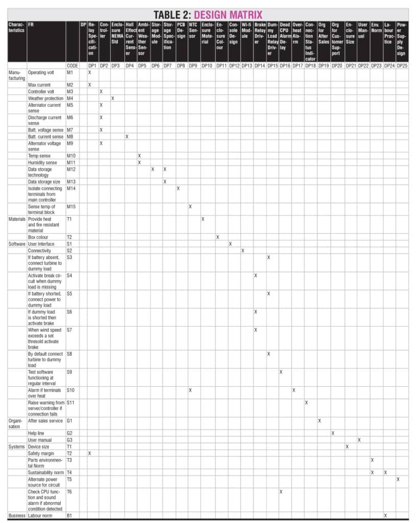
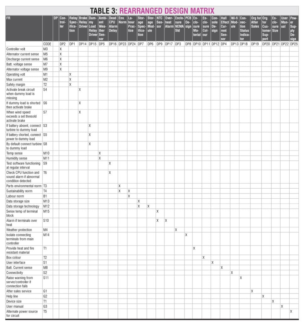
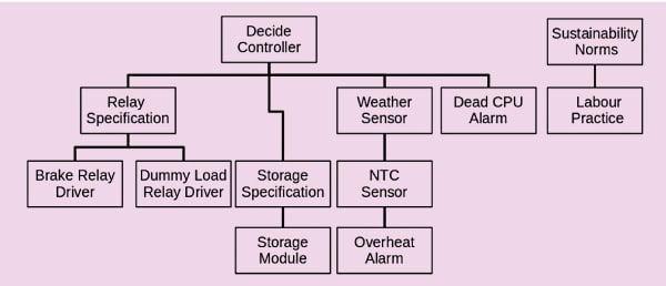
The design matrix has two parts. The lime-colour-shaded part is a diagonal matrix, and we can choose its design parameters without worrying about other parts. The pink-shaded part forms a sort of a triangular matrix, where the parameters affect various functional requirements, but their relationships follow a hierarchy. To organise our decision-making process, we can use a design tree (Fig. 4). This tree helps us set the order in which we make our design decisions.
When creating the decision tree, we follow the order of the decision matrix while considering which decisions are more important. The design matrix serves as a helpful guide. The decision tree illustrates the technical hierarchy of the decisions. Here, we discovered that we missed out on deciding on the box material. We need material that can withstand high temperature and occasional flashes in the terminal connection part. Mild steel is a good choice for that application. But we need a non-metallic enclosure for the Wi-Fi module. In this section, we shall use acrylic. We also decided on the mode of after-sales support and the user manual. In Table 4, you can find the ultimate design parameters we chose for the charge controller.
| Table 4: Design parameters | ||
| Design Parameter | Code | Decision |
| Controller | DP2 | ESP 12F |
| Relay specification | DP1 | A31ACQ24VDC1 |
| Brake relay driver | DP14 | BC148 |
| Dummy load relay driver | DP15 | BC148 |
| Ambient weather sensor | DP5 | DHT11 |
| Dead CPU alarm delay | DP16 | 555 and buzzer |
| Env. norm | DP23 | No lead soldering |
| Labour practice | DP24 | Fair employment practice |
| Storage specification | DP7 | 32GB SD card |
| Storage module | DP6 | SPI SD card module |
| NTC sensor | DP9 | 10D9 thermistor |
| Overheat alarm | DP17 | BC148 and LED |
| Enclosure NEMA standard | DP3 | NEMA 3R |
| PCB design | DP8 | Glass epoxy PCB |
| Enclosure material | DP10 | MS for terminal area, acrylic for Wi-Fi area |
| Enclosure colour | DP11 | Black |
| Console design | DP12 | Minimalistic on the box, HTML form for remote access |
| Hall effect current senser | DP4 | WCS-1600 Hall Effect current sensor |
| Wi-Fi module | DP13 | ESP 12F |
| Connection status indicator | DP18 | LED in controller, on soft interface |
| Org for after sales | DP19 | Web-based CRM |
| Org for customer support | DP20 | Answering machine for tech support |
| Enclosure size | DP21 | 250 x 200 x 80 mm3 |
| User manual | DP22 | Online manual |
| Power supply design | DP25 | DC-DC converters |
QFD analysis and the axiomatic design approach share similar scopes. In QFD analysis, design parameters are obtained through benchmarking, while the axiomatic process examines intrinsic dependencies to derive design parameters. When we apply the axiomatic process after QFD, it not only validates the initial design but also helps uncover any missed details from the QFD analysis.
The axiomatic process is a great way to organise the logical steps in software development. Many of our design goals will be achieved through software. The axiomatic decision tree and decision matrix help establish the sequence of actions to be taken in the program.
Soumyanath Chatterjee is former TVS Motors Chair Professor at Industrial and Systems Engineering Department, IIT Kharagpur. His expertise is in Product Development and Supply Chain Management