


The sky-rocketing cost of energy production has necessitated a more efficientenergy consumption process. This has brought revolution in electrical equipment manufacturing and energy metering infrastructure. Home area network (HAN) is an advanced electrical ecosystem in which a smart utility meter and HAN devices communicate with each other to control the energy consumption profile. Armed with the latest technological advancements in the fieldof energy utilisation, HANs are ready to supplant the traditional electrical ecosystems at home.
A basic HAN device has a two-way communication link with a utility meter and optionally with other devices in a HAN ecosystem, sharing energy consumption data of the equipment it is connected to and also receiving commands to turn off or hibernate the equipment when unused.
This low-cost device can be hooked in the existing electrical infrastructure without the need to replace, renovate, alter or rework the infrastructure. The power consumption is very low (in microamperes) when it’s not in use. The following sections describe certain enhancements to the basic HAN device architecture which extend its capability and feature-set.
Architecture
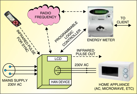
The HAN device can be considered as an intelligent power socket, which at one end connects to the normal power socket and on the other end offers pluggable connection interface for home appliances, e.g., microwave and air-conditioner. It can be controlled directly by the utility meter over wireless interfaces like radio frequency (RF) or wired interfaces like power line communication (home plug, etc). Additionally, its firmwarecan be upgraded over the RF/programmable logic controller (PLC) interface by the utility meter. Various energy parameters of the device can be displayed on the LCD. It also supports battery backup option for maintaining the time and date.
Fig. 1 shows the application diagram of the HAN device. The device consists of a microcontroller, 230V-3.3V converter, relay, signal conditioning circuitry, infrared (IR) interface (supporting both transmitter and receiver), LCD panel and RF/power-line communication physical layer.
Its main operational features are:
- Very low current consumption (10 μA) when it’s not functional
- Very low run current (10 mA); 40 mA at full load
- Fully controlled by the energy meter
- High-voltage cut-off to save the appliances
- Wireless communication over 2.4GHz Zigbee
- Month-wise information storage of the power consumed
- Fully-functional system starting from 90V AC to 300V AC
- Easy to hook on to the network
- Compact in size
Role of various components
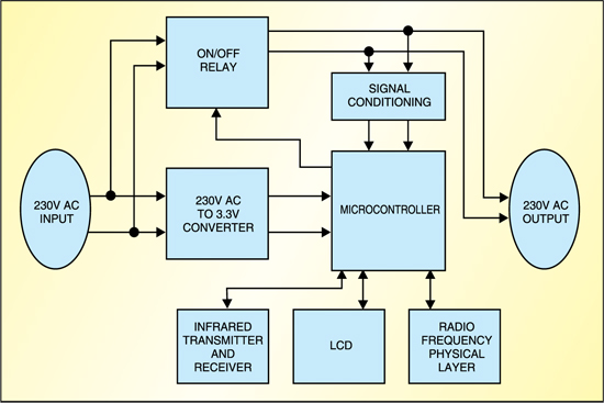
Fig. 2 shows the block diagram of the device components. The role of these components is described below:
Microcontroller. The microcontroller or system-on-a-chip (SoC) plays a pivotal role in the device operation. In addition to controlling other components, it stores the application firware in its internal Flash memory. For supporting various functionalities of the HAN device, the microcontroller should be equipped with the following features:
- Low-power processing core with the capability to perform complex arithmetic operations required for energy calculation
- Suitable physical-layer communication interface for RF or power-line communication, if used
- On-chip Flash memory and static random-access memory for storing application firmware and faster operation
- LCD driver for LCD display
- Interfaces like universal asynchronous receiver/transmitter, which can support infrared communication
- High-resolution analogue-to-digital converters (ADCs) with programmable gain amplifierfor voltage and current measurements
- Input/output (I/O) ports for driving relays
- Real-time counter for time keepingThe microcontroller senses the voltage and current through the signal conditioning circuit along with the ADC and programmable gain amplifierto calculate root mean square (RMS) voltage and current values, instantaneous energy consumed and total energy consumed over a period of time (one month or longer). It then sends this data to the utility meter through RF or power line communication and also displays it on the LCD. When a command to turn off the device is received, it drives suitable logic on its I/O ports to operate the relay.
The microcontroller gets its power supply from the power line through a 230V-3.3V converter. The converter can be suitably configuredaccording to the operating voltage of the microcontroller. The on-chip Flash firware can be updated over the RF or PLC interface by the utility meter. The protocol and exact details of frmware updation depend on specific implementations.
Signal conditioning. The signal conditioning unit consists of an analogue front-end for voltage and current measurement. The line voltage is measured by first down-sizin it with a resistor ladder, thereafter direct-current (DC) filteringand DC biasing.
Compared to voltage measurement, current measurement is less involved. First, the line current is downsized using a current transformer and then passed through a small value of high-precision shunt resistor. The voltage drop across this shunt resistor gives a measure of the line current. As this voltage drop is very small, it is suitably amplifiedbefore being fed to the ADC.
The amplifierconsists of programmable gain stages for amplificationof only the alternating-current (AC) components, thus preventing the amplifie output from saturation.
Infrared interface. The infrared interface can be configuredsuitably according to the range and power consumption. It provides remote configurationsupport for the HAN device, enabling the user to remotely turn on/off the home appliance connected to the HAN device. The protocol and exact details of operation can be flexiblychosen for particular implementations.
LCD panel. The LCD panel displays the instantaneous energy consumed, total energy consumed last/current month, date and time of the day, RMS voltage and RMS current. It inherits some of the utility meter display, thus acting as a low-accuracy but smart AC energy meter.
In a nutshell, the above architecture conceptualises a cost-effective and extremely versatile HAN device, which is replete with all the essential HAN device features along with the support for advanced features like firmwar upgrade and full control of appliances over RF/PLC interface. It also doubles as a low-cost smart AC energy meter, providing round-the-clock energy consumption details of the home appliance.
Though the device is depicted here as a standalone intelligent power socket, it can also be implemented inside home appliances.
Manish Sharma and Manish Jindgar are appli-cations engineers at MSG IDC Solution Center and Biswaprakash Navajeevan is senior design engineer at MSG India Design Center, Freescale Semiconductor, Noida