


Electronic lockers are commonly used for home security applications. Traditionally, the design is consists of an MCU device that receives the input from a mechanical keypad, drives a motor to open and close the door, and outputs the results on an LCD or also speaker/Buzzer for tone.
MCUs with powerful IDE tools help developers to design their applications quickly and with ease. MCUs with different programming interfaces and compilers help designers to build an industrial ecosystem. MCUs with Fingerprint, wireless connectivity and Capacitive and/or Inductive sensing technologies enable designers to design more robust and advanced solutions. This article discusses design techniques, design challenges and future enhancement for MCU based Electronic Safe Locker.
Theory
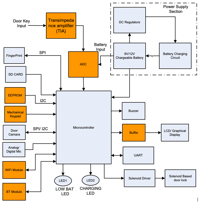
Electronic lockers are becoming more advanced with the boom of the IoT (Internet of Things) Era. Traditionally, 8bit/16bit/32bit MCUs are used to control the entire system. The MCU receives the user code through a mechanical keypad (user code), Fingerprint sensor or SD card (through SPI interface). The MCU stores the users’ code into internal or external EEPROM through I2C/SPI interface. Once the user code (6 digit numbers) matches, the door will open. In such cases, the electronic locker will lock up due to multiple wrong entries or due to the malfunctioning of batteries; users will have to use a master key to unlock the safe. The buzzer provides the tone for every Keypress, MCU drives Buzzer with PWM (Pulse width modulator) output. IDE tool supporting configurable PWM frequency helps the engineer to provide different options in the final application. PWM based control mechanism used for driving solenoid Driver for opening and closing of the door. Normally, fireproof safe is recommended to protect important document paper valuables protected from fire.

This is a battery-operated system, therefore MCUs with low power consumption is a must for the design. Re-chargeable batteries are preferred in this application, where users can replace the battery from the back-side compartment. In addition, MCUs with battery charging and monitoring capability and working on lower voltages suits in this application.
It reads battery voltage through internal/external ADCs and gives indication with “Low Battery” and “Charging” LEDs. The MCU should support sleep, hibernate mode with minimum power consumption and displays the status of keypress on using LED indication or on LCD display. Most often, LCD displays without backlight are used for this application due to less power consumption. For the more advanced designs, a Graphical Thin Film Transistor (TFT) display is used, where the MCU uses external buffers, and level translators to drives the external displays. In addition to the hardware aspects, developing display algorithm software and supporting display software libraries also plays an important role in the design.
Advanced Electronic Safe Locker solution
MCUs paired with pre-certified WiFi-BT modules enables users to send authentication code and unlock the safe using a smartphone (iOS or Android). It also helps to store user’s info to a cloud-based system.
Door cameras (I2C/SPI based) help in monitoring and recording while users are using the safe. MCUs that can interface with digital and Analog Mic with speaker interface will help in audio authentication based security system.
MCU supporting security options like one time programming (OTP) will help developer to load final code into the MCU at production stage which cannot be hacked by any other developer.
MCU supporting Non-volatile memory prevents password erasure, when the battery is low.
What can be improved
Mechanical Keypads can be replaced with CapSense (capacitive-sensing) or MagSense (inductive sensing) keypads with different varieties and size of CapSense pattern that will bring down the cost of the overall solution, developer can provide CapSense detection, Proximity (Keypad gets activated once user’s hands come near). CapSense supports water proofing and water tolerance algorithm, it helps to protect the safe in case of emergency water situation. IDE supporting CapSense and Inductive sensing application helps users to develop the entire application in quick turnaround.
PSoC MCU is a combination of a MCU with programmable logic and high-performance analog to digital conversions and commonly used fixed-function peripherals. The PSoC MCU family is made up of 8bit (PSoC 1 and PSoC 3), and 32 bit MCUs (PSoC4, PSoC5 and PSoC6). They have flash memory up to 2MB, SRAM up to 1MB and internal EEPROM up to 2KB (flash can be used to emulate EEPROM). PSoC works on ultra-low power mode. In low power mode, it consumes <1µA current, making it useful when operating safe in standby mode.
PSoC MCU has an internal RTC component for real-time measurement. It does not require external clock/oscillator circuitry. PSoC supports USB 2.0 and 3.0 interface, allowing the user to interface external memory through USB 2.0 and 3.0. It supports Secure Digital (SD) card interface. PSoC MCU has internal PWM, which is used for controlling and varying the tone of the buzzer for every keypress in low end electronica safe applications. The duty cycle of the PWMs is varied based upon the speed required as set by the user through the GUI interface. PSoC MCU has an internal DAC, which can be used for controlling speaker volume and performs mute function for the audio speaker.
PSoC MCU has internal Op-amp, Comparators and 16-bit 1MSPS Successive approximation ADC with differential and single-ended modes including sample-and-hold (S/H) capability which is used to measure different sensor input and Battery monitoring. so, it does not require external amplifiers, ADC and comparators for electronica safe application.
PSoC MCU has operating range of 1.71V to 5.5V so it can be easily interface with external peripherals for other applications. PSoC supports low operating voltage up to 1.71V and ultra-low power (it consumes <1µA current) operation along with Hibernate and Deep Sleep modes which allow wakeup-time versus power trade-off it will help to support larger battery life/ power supply life.
PSoC MCU supports two independent run-time reconfigurable Serial Communication Blocks (SCBs) with re-configurable I2C, SPI, or UART functionality which will be helpful in electronica safe solution for internal and external peripheral communication.
PSoC MCU supports CapSense and Inductive sensing component which support manual and auto tuning which will be helpful in waterproofing application for electronica safe applications. PSoC directly drives LCDs and graphical displays for displaying different menu options. The PSoC Creator IDE tool has readily available component block for designing interface and logic like SARADC and PGA for analog sensors and other analog inputs. The PWM, CLK, MUX and Comparator components are used for electronica safe application. The character LCD and segment LCD components directly (does not require external buffers) drives LCD/graphical LCDs. It also has the RTC component for real-time measurement. PSoC Creator has an internal system clock and does not require external clock/oscillator circuitry. The other components include Timer, Buzzer, CapSense, Segment LCD, Character LCD, Graphical LCD etc.
PSoC Creator also enables the user to make use of an entire tools ecosystem with integrated compiler tool chains, RTOS solutions, and production programmers. With PSoC Creator IDE tool customers can create and share user-defined, custom peripherals using hierarchical schematic design. Customers can automatically place and route select components and integrate simple glue logic, normally located in discrete devices.

Design challenges, System level Limitations
- Low cost front panel design with different features like Buttons, LEDs and Smartcard interfaces. PSoC Supports CapSesne technology, Using PSoC in the design CapSesne based Button and proximity can be implemented for the front panel design. Meeting CapSense performance (Signal to noise ratio) with nearby LEDs (PWM based) on front panel is a design challenge for system designer.
- As this solution is expected to work for 24 X7 (24hours in 7 days) continuously, component selection and reliability is a design challenge for system designer.
- Fault detection and recovery mechanism is required for continuous operation, Fault recovery system using microcontroller is a design challenge for system designer.
- As this solution involves electro-mechanical construction, designing a compact and cost effective electro-mechanical solution is a design challenge for system designer and certifying this electro-mechanical design with EMI/EMC standards is a design challenge for a system designer
- Implementing water proofing and water tolerance features are the design challenge for the system designer. Implementing auto-tuning with variation in trace capacitance, variation in CapSense button and shape are the design challenge for the system designer also implementing the CapSense sensing with thicker keypad material and meeting CapSense sensitivity with that type of materials is the design challenge for the system designer.
Conclusion
Electronic safe lockers using microcontroller for user interfaces (Keyboard, LED and LCD display, Smartcard interface), Buzzer control and for detecting Analog inputs like Battery voltages. PSoC MCU is a combination of Microcontroller and ASIC. Using PSoC in Electronic lockers one can reduce the complete product cost (by reducing the BOM cost) and project cost (Implementation in PSoC Creator IDE tool).
Ronak Desai is Sr. System engineering manager at cypress semiconductor with total 19+ years of industrial experience worked extensively in Embedded hardware and Software platforms with good knowledge of microcontrollers, Embedded, SET-TOP BOX, RF and CATV domains. He is IPC CID (Certified interconnect Designer) certified for embedded technology.