


In recent months, there has been a move to integrate capacitive-touch and capacitive-proximity user interfaces (UIs) into lighting applications. The simplicity of the UI, the ability to use irregularly-shaped sensors and the ability to seal the UI is advantageous for creating pleasing and low-maintenance LED interfaces. Unfortunately, differences in technology and techniques between lighting and touch-sensing can create conflicting design goals, particularly in the cost-constrained arena of architectural lighting. Let us see how we can bridge this gap.
Getting started with capacitive touch
Let us start with a basic overview of capacitive touch. A capacitor is essentially two conductors separated by an insulator. Depending upon the type of insulator, the area of conductors and the distance between these, the capacitor will have more or less capacitance. The following equation shows the basic relationship between various factors. C represents capacitance of the capacitor and A represents area of the overlap between the two conductors, the two physical constants ε0 and εR represent permittivity of free space (ε0) and relative permittivity (εR) of the insulating material, and D represents distance between the conductors.
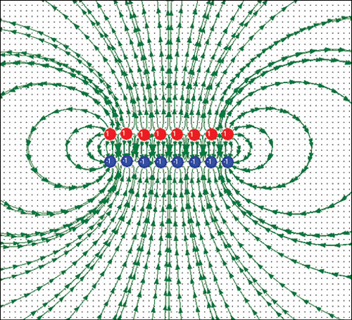
While the space between the plates usually contributes majority of the capacitance, there are also electric field lines connecting opposite sides of the capacitor that contribute to the capacitance of the capacitor. See Fig. 1 for an example plot of the electric field lines for a typical two-plate capacitor. In a capacitive-touch system, it is the electric field lines that project out from the capacitive, rather than the lines between conductors, that touch sensors utilise to detect a touch.
How it works
Human beings, and in fact the majority of carbon based life, are composed of a variety of chemical compounds mixed with a large quantity of water. Water is a fluid composed of electrically-polarised molecules, which means, an electric field can polarise molecules in water very easily. As a result, water based and carbon based life have a very high relative permittivity (εR>60), so there is a very pronounced effect on electric fields. That is what allows the usage of capacitive-touch interfaces (Fig. 2).
Typically, human beings show up as an increase in the capacitance of a sensor. So, all we need for a capacitive-touch or capacitive-proximity interface is a method for measuring the capacitance of the sensor to a sufficient resolution and a conductive sensor pad. (Note: The other conductor of the sensor is typically the electrical ground of the circuit, and the actual conductor is the ground of the circuit. For line-operated systems, this ground is typically earth-ground. So, line-operated systems actually enjoy greater touch sensitivity because we are in close proximity to a lot of earth.)
The challenge
So, all we need is a means to measure capacitance, right? Well, in a perfect world, yes! Unfortunately, we live in an imperfect and somewhat noisy world, so we actually have to add a few qualifiers to that statement. What we actually need is a method for measuring capacitance that is both low-impedance and has low-susceptibility to noise. The low-impedance part prevents external electric fields (conducted noise) from affecting the capacitance measurement, and the low-susceptibility to noise prevents external RFI (radiated noise) from affecting the capacitance measurement.
Conducted noise. If the capacitance-measurement system has high levels of conducted, common-mode noise on its power supply, it will look like noise is being injected into the touch-sensor. Remember that the circuit cannot tell the difference between it moving up and down electrically, and the sensor being drug up and down electrically. So, conducted noise looks to the circuit like noise on the sensor. By using a low-impedance measurement system, we reduce the effects of conducted noise by dragging water molecules of the user up and down in time with circuit-ground, and limit the effect of the ambient-ground pulling on our sensor through the user.
Removing external noise. To subtract out the external noise, we typically use a differential-measurement method, if possible. While it would be great if we could tap into the user’s ground for this function—it is generally problematic to connect to the user’s ground. So, instead, we try to do two measurements, one with a positive charge on the sensor and one with a negative charge. When we subtract the two, we get an approximation of a differential measurement that is good for most low-frequency noise.
i can join with u