


Network failures, whether due to human error or faulty technology, can be very expensive for users and telecom service providers alike. As a result, the subject of so-called fall-back mechanism is currently one of the most talked about in the telecom world. A wide range of standardised mechanisms is incorporated into synchronous networks in order to compensate for failures in network path/elements and to provide highly-available telecom networks.
Automatic protection switching (APS) is a fault-tolerant topology that is used for providing backup to telecom networks. For network survivability, in the event of failure in a network element or link, APS involves reserving a protection channel with the same capacity as the channel or facility to be protected. In the event of signal-fail (SF) or signal-degrade (SD) condition, the working line switches automatically to the protection line within a few milliseconds.
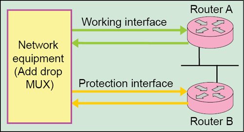
Fig. 1 shows basic APS configuration on network elements, for example, routers/nodes A and B. Here, node A is configured with the working interface and node B is configured with protection interface. In a router configured for APS, configuration for the protection interface includes the IP address of the router (normally its loopback address) that has the working interface. Normally, the working and protection interfaces are connected to a network element of the transmission system, typically, an add-drop multiplexer (ADM).

In the event of failure on working interface of node A, the connection automatically switches over to the protection interface on node B. On the protection circuit, K1 and K2 bytes from the line overhead (LOH) of the synchronous digital hierarchy (SDH) frame indicate the current status of the APS connection and convey any requests for action.
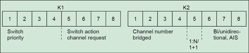
K1 and K2 bytes. The K1 byte in SDH configuration contains switching pre-emption priorities (in bits 1 to 4) and channel number of the channel requesting action (in bits 5 to 8). The K2 byte contains channel number of the channel that is bridged onto protection (bits 1 to 4) and mode type (bit 5); besides, bits 6 to 8 contain various conditions, such as multiplex-section alarm-indication signal (MS-AIS) and indication of unidirectional or bidirectional switching (Fig. 2).
The APS is very extensible in terms of topologies (for example, rings) and flexibility (for example, link-capacity-adjustment scheme (LCAS) service restoration). Basically, two types of protection architectures—linear protection and ring protection—are distinguished in APS. The linear-protection mechanism is adopted for point-to-point connections. But ring-protection mechanism can take on many different forms. Both mechanisms use spare circuits or components to provide the back-up path.
Also Read: Interesting Electronics Project
Linear protection
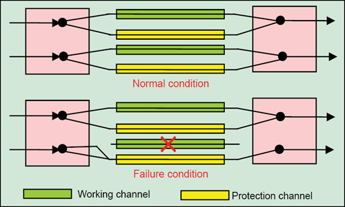
1+1 APS architecture. The simplest form of mechanism for network survivability in the event of network failure is 1+1 APS. Here, each and every working transmission path/line/channel is protected by one protection path/line/channel (Fig. 3). At the near end, the signal is bridged permanently, that is, split into two identical signals, and sent over both the working and the protection lines simultaneously. At the far end, signal selection is made on the basis of switch initiation/trigger criteria, which are signal fail (SF), signal degrade (SD), loss of signal (LOS) or loss of frame (LOF).
If a defect occurs, the protection agent/switch in the network elements at both ends switches the circuit over to the protection line. Switching at the far end is initiated by the return of an acknowledgment in the backward channel. 1+1 architecture includes 100 per cent redundancy, as there is a spare line for each working line. This architecture is simple for implementation and results in fast restoration. But, its major drawback is the wastage of bandwidth, since no useful traffic travels through the redundant paths.
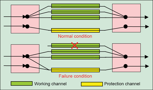
1:N APS architecture. Economic considerations have led to the preferential use of 1:N architecture, particularly for long-distance paths. In this case, a single back-up line protects several working lines (Fig. 4). When the primary path/channel fails, the two ends of the affected path are switched over to the back-up line/channel. During normal operation, no traffic or low-priority traffic is sent through the protection/redundant path.
When any failure occurs (such as, fibre-cut), both the source and destination switch onto the redundant or alternate path. Here, all switching is revertive, which means, the traffic shifts to the working line as soon as the failure is corrected. The reserve circuits can be used for lower-priority traffic, which is simply interrupted if the circuit is needed to replace a failed working line. Although network utilisation is better in this architecture, it requires signalling overhead and also results in slower restoration.
Ring protection
A ring is the simplest and most cost-effective way of linking a number of network elements. The greater the communication bandwidth carried by transmission media, the greater the cost advantages of ring structures as compared to linear structures. Various protection mechanisms are available for ring architecture, such as, unidirectional, bi-directional, revertive and non-revertive connections.
Unidirectional mode means that the two network elements (NEs) choose independently which circuit to receive, without negotiation. In all the modes, the working and protection interfaces receive the same payload from add-drop multiplexer (ADM), but only one is selected or currently active. The deselected interface is held in a ‘line protocol is down’ state and is completely removed. Only the selected interface actually processes the payload.
In bidirectional mode, receive and transmit channels are switched as a pair. But transmit and receive channels are switched independently in the unidirectional mode. For example, in bidirectional mode, if receive channel on the working interface has a failure event, both transmit and receive channels are switched.
In revertive connection, the hardware switches back to the working line automatically after repair of the working line or after the elapse of a configured period. In the non-revertive connection, if a failure condition occurs, the hardware switches to the protection line and does not automatically revert to the working line.
Unidirectional rings. In ring topology, traffic is transmitted simultaneously over the working and the protection lines. If there is an interruption, the receiver switches to the protection line and immediately takes up the connection. This switching process is referred to as line switching. A simpler method is to use the so-called path-switching ring in which a backup path is used from the source to its destination to bypass the failure.
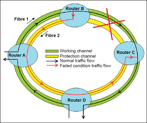
Fig. 5 shows the basic principle of APS for unidirectional rings. Let us assume that there is an interruption in the circuit between the network elements, say, router B and C. In this situation, node adjacent to the fault will detect the condition and start the APS protocol. K1 and K2 bytes of the SDH frame indicate the current status of the APS connection and convey bridge requests, node information, type of failure, etc to the affected nodes. Each node detecting a fault sends an APS request to the node to which it was connected in the direction of fault. The connection is therefore switched to the alternative path in network elements.
Bidirectional rings. In this network architecture, connections between network elements are bidirectional. Often, bidirectional line-switched ring (BLSR) is used in which the overall capacity of the network can be split up for several paths, each with one bidirectional working line. For unidirectional rings, an entire virtual ring is required for each path. In a BLSR, every link can carry both the working and protection traffic at the same time.
BLSR has two variants, namely, four-fibre BLSR and two-fibre BLSR. In a two-fibre BLSR, traffic is sent over both the fibres by utilising only half the capacity on each fibre and keeping rest half of the capacity reserved for protection.
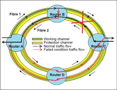
In four-fibre BLSR, two fibres are used as working line and the other two are used for protection (Fig. 6). Each pair of fibres transports working and protection channels. This results in 1:1 protection, that is, 100 per cent redundancy. This improved protection is coupled with relatively high costs.
Ring and span switching mechanisms are used in the event of failure. In span switching, when the source or destination on a link fails, traffic gets routed onto the protection fibre between the two nodes on the same link. And when a fibre or cable-cut occurs, service is restored using the ring switching mechanism. Two-fibre BLSRs also benefit from the ring switching but cannot perform span switching like a four-fibre BLSR.
Let us take an example of network failure in four-fibre bidirectional ring. If a fault occurs between neighbouring elements B and C, network element C triggers protection switching and controls network element B by means of K1 and K2 bytes of the SDH system and traffic is re-routed as shown in Fig. 6.
Conclusion
Network failures are very crucial and have always been a concern of utmost importance. Such failures may result in heavy losses of traffic, leading to complete service outage. In order to safeguard networks from failures, automatic protection switching mechanisms are being widely deployed in long-haul networks as well as in inter-office networks due to their high-efficiency capabilities coupled with very-low (less than 50ms) restoration time.
The author, working with Bharat Sanchar Nigam Limited, holds Ph.D. degree in electronics engineering from Indian Institute of Technology (BHU), Varanasi. He has authored/co-authored more than 25 research papers in peer-reviewed national/international journals. His current research interests include wired and wireless technologies for high-speed telecom services
