


We take batteries for granted and often use them recklessly without taking care of them and their charging systems. This results in their shorter life and sometimes outright failure when we need them the most. The protection mechanisms described here could protect the batteries and their chargers even when these are misused.
Our modern-day lives are quite dependent on batteries, which come in all forms, shapes, and internal chemistries and are found almost everywhere. Batteries that can only convert their chemical energy into electrical energy and their electrochemical states cannot be revived are called primary batteries. Those whose electrochemical states can be revived back, using electrical current, are called secondary batteries or rechargeable batteries.
The secondary batteries are quite interesting in their electrical properties. When these are being discharged they behave like an energy source, but during charging they act as electrical loads. Rechargeable batteries come in different chemistries. The most prolific ones are the various types of lithium-ion (Li-ion) batteries found in almost all portable devices, such as mobile phones, laptops, tablets, toys, etc. We shall be looking at the various battery protection mechanisms used in electronic circuits for such rechargeable batteries.

The lead-acid batteries are either sealed or tubular. These are also used very often in domestic, industrial, and automotive settings and, as of now, form the backbone of electrical energy storage applications, such as domestic and industrial inverters, emergency lighting, and various automotive applications.
The other two most used chemistries for rechargeable batteries are the NiMH (nickel metal hydride) and NiCd (nickel cadmium) batteries. These were till recently used in still photography cameras, however their use in these areas has diminished and taken over by Li-ion batteries. These are still used quite widely in railway applications as battery backup for the coaches.
It is interesting to note that all the above battery chemistries have been known for at least the last 40 years, with the lead-acid ones being known for more than 150 years now. From an electronics circuits design standpoint, the protection mechanisms that we shall discuss apply to all types of secondary (or rechargeable) batteries. Some protections are required during the charging process, while others make sense only during the discharge process.
Thus, some protections are implemented as part of the charger, while others are implemented as part of the battery management system that oversees the charging and discharging process of the battery.
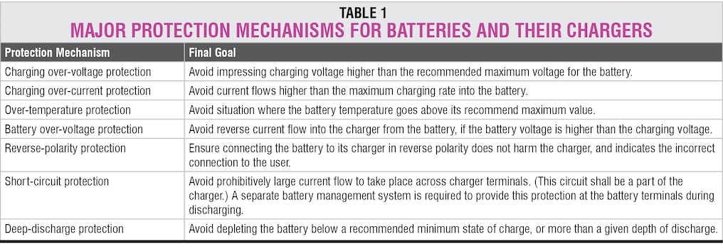
The protection mechanisms we shall discuss are listed under Table 1. It is important to note that these are listed for the complete battery and not for individual cells. Protection of each cell would be part of another article on battery management systems.
Before we get into the details, it would be prudent to discuss the typical charging stages for a battery. Generally, battery charging is divided into three distinct stages. These can then be subdivided into as many as seven different stages based on the state of charge (SoC) of the battery. The SoC is a figure of merit of a battery’s charge capacity and is quite elusive to measure accurately. However, for a large part of the charge-discharge curve of the battery, the SoC can be estimated using the battery terminal voltage.
The three charging stages are bulk, absorption, and float stages. Some battery chemistries are quite sensitive to impressed voltages and hence only expect very slight float voltage and usually require the charging circuit to disconnect once a certain terminal voltage is reached.
The most common charging algorithm used is the CC-CV method, which stands for constant current-constant voltage method. While some chemistries only require a CC method, the others get charged using only the CV method. Variations in the impressed voltage and the permissible charging current result in more charging stages.
Charging over-voltage protection
Charging over-voltage protection mechanism must ensure that during the charging process the battery is not subjected to voltages higher than the maximum recommended value.
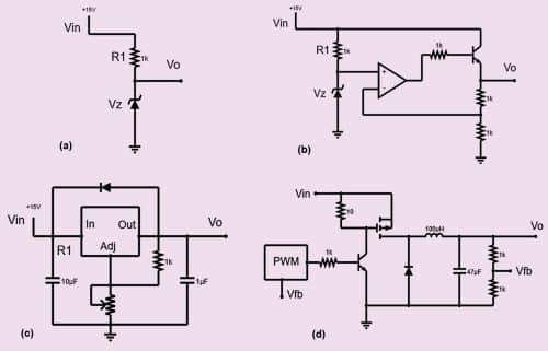
While the battery is in the CV charging phase, over-voltage protection is a continuous control problem, where a complicated PID loop is used to ensure that the voltage is fixed and does not exceed the voltage set point for that phase. Typically, this is achieved using a voltage regulator design, either using a discrete fixed or adjustable voltage regulator IC, or by using embedded code for a microcontroller which produces control signals to keep the voltage to the battery constant.
In the CC charging phase, over-voltage protection is a simpler limiting control problem. Here a comparator circuit in hardware or comparison operators in the microcontroller code can be used to ensure that the impressed voltage is lower than the maximum permissible voltage. Generally, both continuous control and limiting control functions are integrated into the charger to provide reliable control.
Charging over-current protection
This protection mechanism ensures that the current flowing into the battery is kept below a maximum permissible value. It is quite clear that one cannot push current into a load unless the impressed voltage is set to a value such that the required current flows against the load resistance. Thus, voltage control is an essential part of current control.
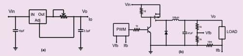
When the battery is in CC charging phase, this protection becomes part of a continuous control strategy, which aims at keeping the current value constant within the given battery terminal voltage envelope. This is generally achieved using a linear or switching regulator design, like the voltage control strategies shown above, where the quantity being controlled is current. While there are tens of ways to create a constant current source, only the simplest ones are presented below for reference.
In CV charging phase, the protection becomes a simpler limiting control problem, where a simple comparator circuit in hardware or comparison operators in the microcontroller code does the task. If the current flowing into the battery (or the load) increases beyond a pre-set limit, the designer can either choose to shut down the charging supply or reduce the impressed voltage to keep the current flowing within a limit.
Most switching power supplies provide overload protection (which is basically over-current protection), whereby the power supply shuts down the output for some time and then rechecks by starting the supply again. In the world of power supplies, this is called the hiccup mode.
In the worst case, the hiccup mode, with its repeated start-stop cycles, can cause permanent damage to some of the control electronic elements, such as op-amps and other control ICs. If the power is only being used for battery charging, then this might be alright. In other cases, where the power supply is shared by other sub-systems, it is best to use a linear current limiting provision of some kind to ensure longevity of the control electronics.
Charging/discharging over-temperature protection
This type of protection for batteries is generally part of the battery management systems. Batteries are electro-chemical products, and hence they are typically sensitive to temperature. In general, heightened temperatures for long times can cause permanent and fatal damage to their cells. This is true for all battery chemistries.
Li-ion chemistries are unique in the fact that they also have a lower temperature limit, below which their operation is not possible. So, for Li-ion batteries both low and high temperature protections are required. This protection is generally provided by using a surface temperature sensor, such as an RTD (resistance temperature device) that changes its resistance based on the surface temperature where it is attached. An electronic circuit is then used to convert this into a proportional voltage (for small distances) or current (for longer distances) that is fed to a comparison circuit or comparison operators in the microcontroller code, which then takes preventive action by disconnecting the charging or discharging paths.
During the charging process, over-temperature condition may occur if the charging current is much higher than recommended. For example, in a lead-acid battery, a 0.1 to 0.3°C charging rate is considered quite safe, while for a Li-ion battery, a 1°C rate is considered alright. Anything higher than these values may heat up the battery.
Over and above the basic preventive actions that the system should take, some systems may also provide active cooling or heating controls to ensure that the battery temperature stays within a prescribed range. Temperature is a relatively slowly changing quantity. In control systems parlance, temperature has a rather large time constant as compared to other physical quantities, such as voltage or current. So, temperature control in battery management systems is mostly implemented using simple on/off control with varying time intervals, depending on how close the temperature is to the limiting value.
Reverse polarity protection
Reverse polarity protection ensures that unintended high current does not flow into or out of the battery. During charging a battery may look like a load, and while discharging the battery acts as a source of energy. Connecting incorrect polarity of the battery to the charger results in a large potential difference and hence an almost uncontrolled current flow ensues, limited only by the resistance of the connecting leads. This large current flow is, most of the times, enough to damage the charger permanently.
The absolutely required protection for such unintended connection error is to clearly and legibly label the positive and negative terminals of a battery in mutually contrasting colours, such as red and blue. This visual feedback is absolutely essential in addition to the + and – marks on the battery terminals.
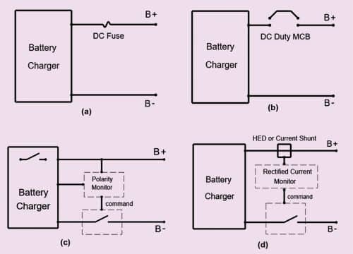
The next simplest mechanism to protect the charger is to install a fuse at the charger output. This fuse must be of adequate current and voltage rating, typically twice the charger’s rated output current and at least twice the charger’s maximum output voltage. Such a fuse is almost always guaranteed to blow up as soon as the battery is connected in reverse while the charger output supply is present. This is also the most common way to provide reverse polarity protection to chargers. This will protect the charger and, in addition, render the charger useless until the fuse is replaced with an equivalent. Since such a fuse blow is rare, these fuse links are installed inside the charger chassis to avoid tampering, which makes the process that much more time consuming.
A much better solution is to create a circuit element that monitors the battery polarity as it is connected to the charger. The circuit could immediately disconnect one or both legs of the charger (the charger terminals) from internal electronics, if an incorrect battery polarity is detected, and would not reconnect until the correct polarity is detected. Polarity monitoring would involve terminal voltage, and for a deeply discharged battery the terminal voltage might be below the threshold, which may give incorrect results.
A further enhancement to the above protection mechanism is to include a rectified current monitor, preferably isolated from the battery supply, across a burden resistance. If the battery is connected with incorrect polarity, there shall be no current flow, signalling to the control system that the battery is not connected properly. The control system can in turn drive a solid-state switch, such as a MOSFET placed in the path of the charger terminal, to disconnect the charger from the battery. Such a mechanism involves no blown fuses and allows the charger to be reused immediately after correcting the battery terminal polarity. Since this is a safety related mechanism, it should be preferably kept separate from the main charging controller to provide feedback to the charging system about battery connections.
Short-circuit protection
It is interesting to note that the above reverse polarity protection mechanisms, which are based on observing current through a burden resistance, can also save the charger from an output short-circuit situation. While this protection would not follow a typical I2T curve, it still provides adequate protection to the charger against large instantaneous current flow.
Some chargers use an MCB rated for the given DC duty at the output of the charger to provide the above protections. However, the MCB is rated only for a few fault events and cannot be reused indefinitely over and over again to break the same current each time reliably. Also, general MCBs are better suited for AC currents, which contain a natural zero crossing that naturally reduces the instantaneous current flow and helps break the current flow with lesser damage to the breaker elements.
Battery over-voltage protection
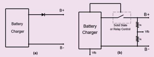
In some cases, battery chargers may be subjected to battery voltages higher than their maximum output voltages. In such cases, there is a chance of reverse current flow into the charger electronics, or higher voltage stresses across the main switching elements. The most common way to protect against this is to include a diode of rated current forward biased towards the positive terminal of the charger, that is, with its cathode pointing towards positive terminal of the charger.
The downside of such an arrangement is that during regular current flow, there can be significant power dissipation in the diode. For example, at 20A and 0.7V drop across the diode, the diode dissipates 14 watts, while the diode also reduces the charging voltage by its forward drop value.
A slightly better way is to use a MOSFET switch, and drive it based on a signal that ensures that the battery voltage is always lower than the charger voltage. The lower channel resistance of a MOSFET, called RDS-ON, results in reduced power dissipation as compared to the diode example. For a typical RDS-ON value of 20 mOhm, at a charging current of 20A, power dissipation would be about 8 watts.
Another scheme can use a normally-open contact of an electro-magnetic relay and drive the relay with the same above signal. This allows almost zero power dissipation across the switching contacts. Both these types of switches need to have higher voltage ratings than the main charging switches.
Deep-discharge protection
This is an often overlooked yet extremely important protection mechanism for the battery itself. This arrangement is typically part of a charge-controller and/or battery management system. It paves the way for enhancing the battery’s life significantly. Once a battery discharges to a very low voltage, such that its depth of discharge reaches approximately 80% of its fully charged capacity, any further discharge may turn out to be fatal for the battery.
This applies to all battery chemistries, and this fatal electrochemical effect occurs in different batteries via different mechanisms, but the final effect is similar. Except that in the energy-dense chemistries, such as Li-ion, the deep discharge can result in swelling and thermal runaway of the battery. Many informative articles about the deep discharge phenomenon in Li-ion batteries can be found in journals such as Nature.
In lead-acid batteries, deep discharge can lead to ‘shedding’ of the positive active material and shorting of the plates. So, in all cases, deep discharge of batteries is best avoided. The protection here is slightly different, and more robust from idle state mechanism, where the controllers are placed in an idle condition using their sleep modes to save battery current draw on an on-going basis. This protection is used when the battery has actually been depleted extensively.
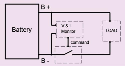
This protection is implemented using a circuit that continuously monitors the battery terminal voltage and battery current draw while it is being discharged, thereby estimating its depth of discharge (DoD) or state of charge (SoC). Once the SoC goes below a certain pre-decided value, the circuit drives a switch that disconnects the battery from the load.
While the main power load is disconnected, trickle current consumed by the control circuitry may still keep the battery discharge going. Though this trickle current may be small, at about 500 to 1000 times lesser than overall current draw, but it is continuous.
And this continuous draw can pull the battery into the fatal zone. Hence, a further enhancement to the scheme ensures that either the control circuitry is also disconnected (good for pure analogue controllers), or the digital controller itself is placed in a sleep condition.
Controllers should be chosen with as low sleep currents as possible. Also, once the battery is disconnected, the electrochemical nature of the battery allows its terminal volage to build up again to a value where the controller might see it as healthy once again. This should not allow the battery to be reconnected to the load, otherwise an on/off sequence would occur, which is detrimental to the battery system and anything that draws power from it.
A separate circuit allows this deep-discharge shutdown to be reset and the battery system to reconnect to the load. However, it is best to interlock this with an input charging supply, such that the reset occurs automatically once charging starts.
VISHAL SAPRE is an Electronics Design professional working with Righill Electrics as GM (Technical). His interests include embedded control systems, IoT, power electronics, and the use of interpreted language systems, such as Python in microcontrollers