Sunday, April 28, 2024

Reference Design For Low Voltage Ceiling Fan 

The design is specifically tailored to control a low-voltage, three-phase BLDC ceiling fan motor with a power output of up to 40 watts. 

reference design for low voltage fan by microchip

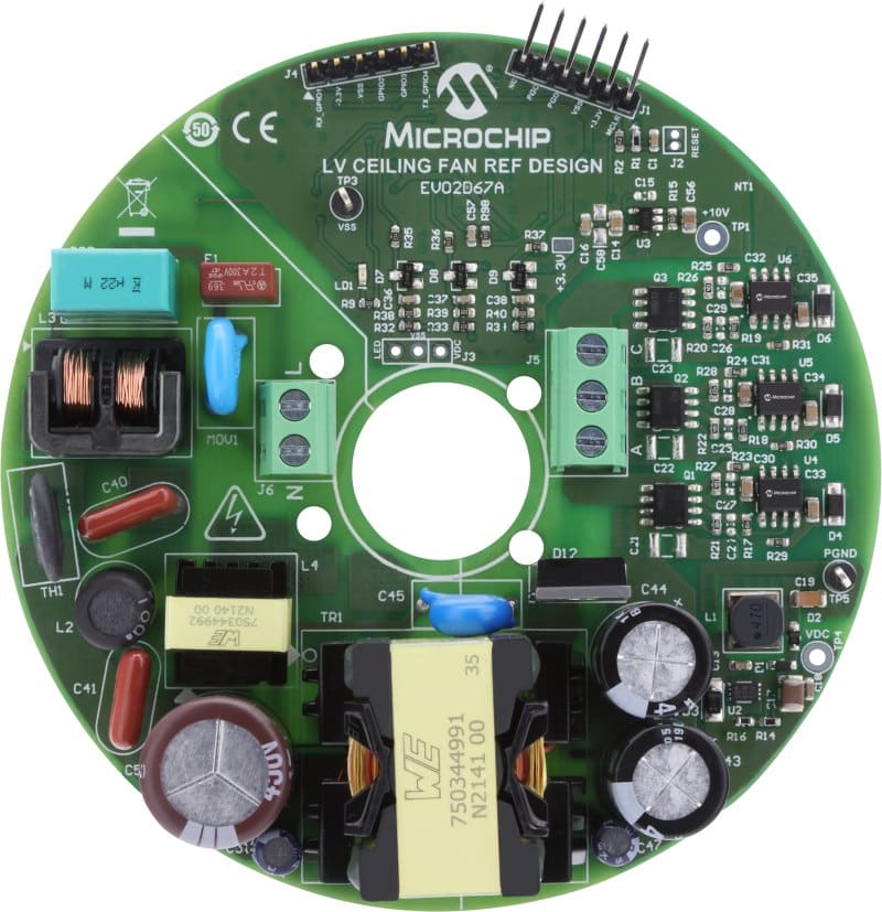
To minimize residential energy consumption, ceiling fans and other household fans are transitioning from large and heavy single-phase AC induction motors (ACIM) to smaller, lighter, and more efficient three-phase brushless DC (BLDC) or permanent magnet synchronous motors (PMSM) that offer higher power density. Microchip has launched a reference design for a low-voltage ceiling fan that provides a cost-effective and energy-efficient solution for a low-voltage PMSM fan. The design can operate a ceiling fan at 300 Revolutions Per Minute (RPM) while consuming approximately 17.5W of power, equivalent to the energy required by two Light-Emitting Diode (LED) bulbs that are approximately 60 Watt. This Reference Design controls a low-voltage, three-phase PMSM/BLDC ceiling fan motor. The board operates from the input AC power within the 90-265 VAC voltage range. The design can drive BLDC/PMSM motors with a power output of up to 40W. 

The Reference Design incorporates several key features such as a three-phase motor control power stage, a 32V, 45W flyback power supply with switched valley-fill power factor correction (PFC), an auxiliary power supply to support the on-board circuitry and external interfaces, DC bus current feedback for overcurrent protection and the implementation of a single shunt current reconstruction algorithm. It also includes DC bus voltage feedback for voltage protection and compensation, an AC voltage measurement circuit, phase voltage feedback for sensorless back-electromotive force (BEMF) control or flying start (windmilling), and an ICSP header for interfacing with a Programmer or a Debugger.

The design is based on the Digital Signal Controller (DSC), dsPIC33CK64MC102 that is equipped with enhanced on-chip peripherals, including high-speed Pulse Width Modulation (PWM), high-speed ADC, operational amplifiers, comparators, communication peripherals, timers, and more. Transitioning from a high-voltage single-phase ACIM to a lower-voltage 3-phase PMSM/BLDC motor necessitates a two-stage power conversion circuit. Firstly, a flyback converter circuit transforms the input power ranging from 90-265 VAC into an intermediate 32 VDC, incorporating high Power Factor Correction (PFC) to ensure energy efficiency. The power factor remains above 0.9, even during low-power scenarios, creating the necessary voltage bus to drive most PMSM motors. The 32 VDC is then reduced to 10V using a PWM DC/DC Converter. Additionally, the 10 volts is further decreased to 3.3V with a highly efficient Low Drop-Out (LDO) Voltage Regulator, serving to power the DSC.

Microchip has tested this reference design. It comes with a Bill of Material (BOM), schematics, etc. You can find additional data about the reference design on the company’s website. To read more about this reference design, click here.

Nidhi Agarwal
Nidhi Agarwal
Nidhi Agarwal is a journalist at EFY. She is an Electronics and Communication Engineer with over five years of academic experience. Her expertise lies in working with development boards and IoT cloud. She enjoys writing as it enables her to share her knowledge and insights related to electronics, with like-minded techies.

SHARE YOUR THOUGHTS & COMMENTS

Unique DIY Projects

Electronics News

Truly Innovative Tech

MOst Popular Videos

Electronics Components

Calculators