


The USB power delivery (PD) battery charger design incorporates a SEPIC power supply that meets the 20V/5A 100W USB PD specification.
A Universal Serial Bus (USB) Battery Charger is a device that has USB ports to deliver power to rechargeable batteries. A power delivery (PD) charger enables fast charging by providing higher power levels than standard USB chargers. USB PD chargers are commonly used for charging smartphones, tablets, laptops, and other portable electronic devices. A USB PD charger is useful for travel, work or study, gaming, emergencies, simultaneous charging, and high-power devices. Microchip has launched the reference design of the USB Power Delivery Battery Charger to simplify the design of chargers. The design offers a simple solution to incorporate multi-cell Lithium-Ion battery charging into existing applications. This reference design greatly minimises the need for extensive engineering board revisions, resulting in significant time and cost savings. With a fully validated solution readily available, valuable engineering resources can be conserved, allowing developers to focus on other critical aspects of their projects.
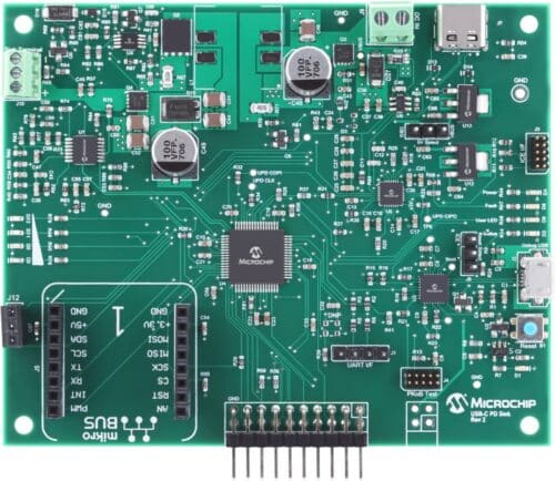
The reference design is based on the ATSAMD21J18A microcontroller, a low-power, 64-pin device featuring a General Purpose ARM Cortex M0+ core. The design features a Pro Kit on Board (PKoB) for USB programming/debugging. The USB PD charger supports two types of expansion headers. One is a 4-pin explained professional (Xplained Pro) power header with an Xplained Pro Input/Output (I/O) header; the other is a microcontroller bus click board connector. The battery charger incorporates a Single-Ended Primary Inductor Converter (SEPIC) power supply that meets the 20V/5A 100W USB PD specification.

The charger utilises a constant current/constant voltage charge algorithm, operating in three primary states, pre-condition, constant current charge, and constant voltage charge. In the precondition mode, the charger limits the charge current to a few hundred milliamps if the battery voltage is too low for full current charging. Once the battery voltage surpasses the pre-charge cutoff threshold, the charger increases the current to the maximum allowed charge current.
The charger maintains a constant current during the charging process until the battery voltage approaches its maximum level. Then, it switches to constant voltage mode. In this mode, the charger periodically checks the battery voltage and adjusts the current if necessary to keep it at or slightly below the maximum voltage threshold. This ensures a stable battery voltage. The charger will continue this process until the charge current drops below a specified cutoff level. At that point, the charger will shut off but will remain active to monitor the battery and perform occasional top-offs as required.
Microchip has tested this reference design. It comes with a Bill of Material (BOM), schematics, etc. You can find additional data about the reference design on the company’s website. To read more about this reference design, click here.
