


 This article describes a method for making an ESP8266-12E/F module programmer and also discusses the support circuitry required for real-time applications.
NodeMCU board is a development kit that consists of ESP8266 Wi-Fi-enabled chip and many other support circuitries. It is a popular board, which is handy to work with Wi-Fi-related projects. But when product development and testing stages are completed, the whole NodeMCU board is not required—only ESP8266 chip is required for the final product. This reduces the overall cost of the product, lowers power consumption, and ensures a smaller PCB footprint and code security.
However, it is not easy to separate ESP8266 chip from NodeMCU board. An alternate solution is to buy ESP8266 chip separately, which is also much cheaper than NodeMCU board. With this option, you can directly burn the code into ESP8266 chip using a suitable programmer, like the one described in this article. After that, you can pull out ESP8266 chip from the programmer and use it in your final product.

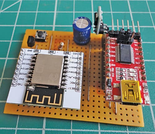
The ESP8266-12 E/F module programmer used by the author is shown in Fig. 1.
The process of designing and building a project using ESP8266 can be broken down into two distinct steps: hardware and software. Hardware revolves around building support circuitry to GPIOs, while software revolves around writing, compiling and loading the sketch into the chip. Such application again involves two stages: development and deployment.
Development stage
During development stage, you need a software development kit (SDK), like Arduino IDE, with ESP8266 Board Manager and supporting libraries, or the newer PlatformIO IDE, for writing the software.
- Software code is flashed into ESP8266 chip using the built-in serial TTL-to-USB adaptor (sometimes called USB-to-UART bridge). For flashing any new software, ESP8266 chip must be rebooted in flash mode, and USB signals from the computer must be converted to serial UART signals and transferred to the chip using Rx0 and Tx0 pins (GPIO3 and GPIO1).
- On NodeMCU board, support circuitry automatically handles all these things in a seamless manner. This makes NodeMCU or similar board, like WemosD1 Mini, popular among hobbyists. Note that, Reset and Flash buttons are also built onto NodeMCU board to help in case auto-loading fails.
Deployment/production stage
During this stage, only ESP8266 chip is required in the final product.
The issue now is to figure out how to use ESP8266-12E/F (or ESP-12E/F) chip and still be able to load the code and develop the software without NodeMCU or similar board. For that, first we need to know the physical size, working, booting and flashing process of ESP-12E/F chip in detail.
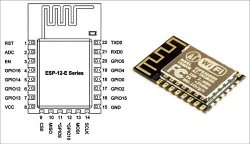
ESP-12E/F module. External size of the module is 16mm x 24mm x 3mm, as shown in Fig. 2. It has 4MB SPI flash and an onboard PCB antenna. Pin pitch is 2mm.
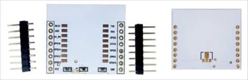
If a general-purpose PCB, which has a pin spacing of 2.54mm, is used for building the project, a breakout board for ESP8266 chip can be used. The breakout board used in this project is shown in Fig. 3. However, if a project-specific PCB is used, the breakout board is not required. ESP8266-12x breakout board is easily available at a low cost.
ESP-12E/F chip is soldered to the breakout board at the given pads, and header pins are also soldered to the breakout board. Header pins are spaced 2.54mm apart. ESP-12E/F module can be plugged into any general-purpose PCB.
There are also three SMD resistors on the breakout board (Fig. 3). On the obverse of the board, there is space for fixing HT7333A, a low-drop 3.3V voltage regulator. Alternately, an external 3.3V regulator may be used for powering the circuit.
Manual ESP-12E/F programmer
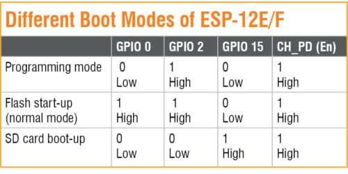
ESP-12x can boot up in three different modes, as shown in the table. We are interested in the first two boot-up modes.
As can be seen from the table, at boot-up, GPIO2 and Ch_PD/En pins should always be held high, while GPIO15 should be held low. While using the standalone ESP-12E/F chip, add 10k/12k pull-up resistors on Ch_PD and GPIO2 pins, and pull-down (10k/12k) resistors on GPIO15 pin. Note that, pull-up and pull-down resistors are prebuilt on the breakout board.
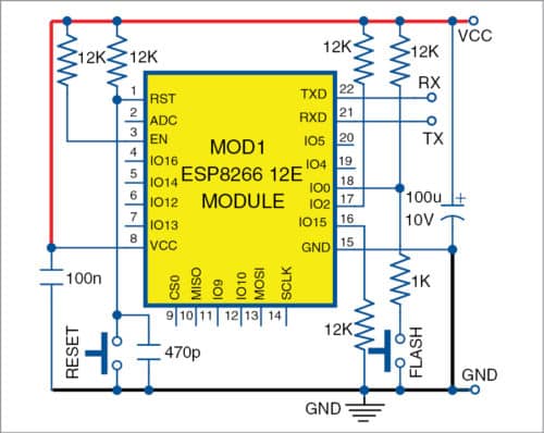
Reset pin and GPIO0 should normally be held high but connected to ground through micro switches, as shown in the circuit in Fig. 4. This is the minimum configuration necessary for using ESP-12E/F module. Every project built around this module should have these five 12k resistors. These resistors are prebuilt on NodeMCU board.
Manually flashing process
A manual ESP-12E/F programmer is shown in Fig. 4. For manually flashing any sketch/code to ESP8266 chip, first put it in flash/programming mode step-wise as follows:
- Press and hold Reset (S1) and Flash (S2) buttons.
- Release S1 while holding S2 down. This is equivalent to power-on while GPIO0 is held low.
- Release S2 after ESP8266 boots up.
- Upload the software via Tx and Rx pins. Since computers no longer have hardware serial ports, a USB-to-UART converter may be used. This conversion happens on NodeMCU via built-in CH340G or CP2102 USB-to-UART chip. FTDI USB-to-UART module, which is available easily, is used for this programmer.
- Once the flashing process is completed, restart ESP8266 by pressing switch S1 to boot ESP8266 in normal mode.
Automating flashing process
While the above process requires manual intervention every time new software is flashed, we need the convenience of loading the software code similar to the experience of using NodeMCU. This process can be automated by using data terminal ready (DTR) and ready-to-send (RTS) signals of the USB-to-UART chip, which are used for asserting Reset and Flash (GPIO0) pins on ESP8266 chip.
DTR and RTS pins are conveniently accessible on the popular FTDI module built around FT232x USB-to-UART module (shown in Fig. 5). External USB-to-UART modules using CH340 chips are also available, but DTR and RTS pins are not accessible on these modules.
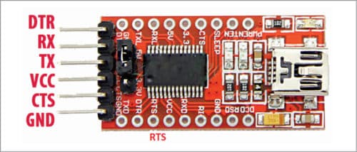
RTS signal on FT232x USB-to-UART module is available on a separate pin, as shown in Fig. 5. For ease of use with the programmer, mount male header pins to the module where all the required outputs (holes) are available. An optional serial adaptor, consisting of six pins, is mounted horizontally on the module, rather than vertically.
FT232 module also has an integrated 3.3V level converter for USB I/O. Since ESP8266-12x works on 3.3V, jumper on the module should be set to 3.3V, so that signals are compatible with ESP8266. 3.3V can also be used to supply external logic. However, maximum current rating in FT232 is 100mA, while ESP8266-12E/F can draw peak currents of 170mA. To prevent damage to FT232 device, an external 3.3V module is used to power ESP8266-12E/F.
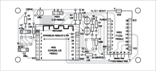
The programmer circuit
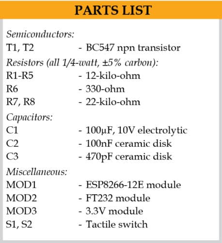
The circuit diagram of the automatic programmer is shown in Fig. 6. It is built around ESP8266-12E module (MOD1), FT232 module (MOD2), 3.3V module (MOD3), two switches (S1 and S2), two BC547 transistors (T1 and T2) and a few other components.
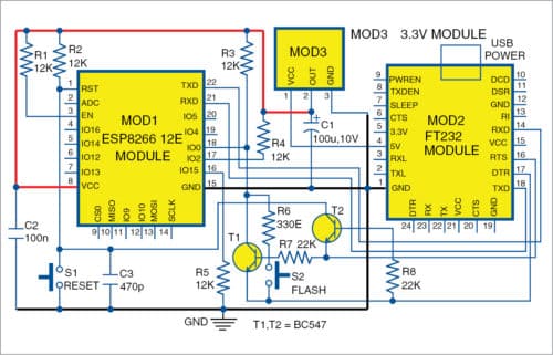
Automatic ESP-12E/F programmer circuit is similar to the manual programmer discussed above. RTS signal is used for resetting ESP8266, while DTR signal is used for putting the chip in flash mode. T1 and T2 are used so that ESP8266 is not reset when both DTR and RTS signals are low. On detecting upload command, ESP module is automatically put in flash mode, and a new sketch can be uploaded to it seamlessly. In the absence of upload command, ESP-12E/F starts in normal mode, and the programmed ESP-12E/F board can be tested or used in an application.
To test ESP-12E/F board, a simple LED blinking application is presented in this article. The software code (NewBlink.ino) is written in Arduino programming language.
How to use the programmer
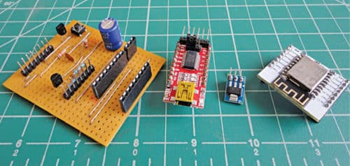
The programmer can be built on a general-purpose PCB, as shown in Fig. 7, or on the designed PCB, as shown in Figs 8 and 9.
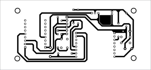
Download PCB and Component Layout PDFs: click here
Download Source Folder
Female Berg strip connectors are used for plugging in ESP8266 chip and FTDI board (FT232 module) on the programmer board. Mount the modules and connectors on the PCB. Make sure that the modules are plugged in the correct orientation.
Now, connect FT232 module to the computer via a USB cable. Open Arduino IDE and write your code, or open the existing code stored in your computer. Here, you just need to open the code (NewBlink.ino) of the LED blinking application.
Select the correct Com port in Arduino IDE and set the board as NodeMCU 1.0 (ESP-12E Module). Check that the upload speed is 115200. Compile and upload as you would normally do using NodeMCU. Built-in LED (on GPIO 2) on ESP-12E/F board will start blinking on successful upload.
The programmed ESP-12E/F module can be unplugged from the programmer and shifted to your project-specific board. You now have a cheaper and smaller version of NodeMCU ready for deployment.
Ashok Baijal is an electronics hobbyist, and an old contributor to Electronics For You magazine.
cool schematic. i must ask, why do you have “flash” button across transistor T1 (that is between DTR and GPIO0) ? . In nodeMCU its between GND and GPIO0 with a 470R in series .
The author Ashok Baijal replies: “The flash button and reset buttons are to be used only if you wish to program the ESP chip in traditional way. As per the circuit design, there is no need to manually press buttons S1 and S2 as this process is automatically handled by transistor T1 (mimic S2 flash button) and T2 (mimic S2 reset button)”
In breakout board three resistor prebuilt,
Why using another three as shown in schematic.
Hi,
Just need to know what is the purpose of C3 capacitor (470pf) ?
Capacitor C3 across reset switch acts as debouncer element to prevent multiple false reset signal.
Hello Sh Ashok, I have to inform readers that the white breakout board cannot be used if the VCC is five volts and one intends to use a AMS117-3.3V regulator on the reverse. The input and outputs gets crossed. However if 3.3 V is used at VCC pin then AMS117-3.3V is not required
Hi Very useful tutorial, i have designed a circuit on bread-board but code was not uploading into ESP12F Module, i have selected the baord as nodemcu 1.0 and also tried with Generic ESP8266, will you help me how to solve this error.
what is the difference when place 10k resistor instead of 12k?