


 Often, we communicate within a known group of office or friends using short key words or phrases. This group messenger can be useful to such small groups for whom a keyword is sufficient to understand the message. The display shows current date and time by default when there is no message and serves as a decorative piece on worktable.
This messenger can hold up to ten messages. On receipt of eleventh message, the oldest message is deleted and the latest is added to the list of messages, using the first-in-first-out principle. It may be used by up to eight persons to communicate with each other using keywords.
Circuit and working
Circuit diagram of the group messenger is shown in Fig. 1. It comprises a 40-pin AVR microcontroller (ATmega32), a long-range wireless transceiver (HC-12), an RTC IC (DS1307), and a 5V regulator IC (7805). A 9V or 12V DC adaptor, or a battery, may be used as power supply for the circuit. All the switches ES1 through ES5 and SS1 through SS8 are tied to a 470-ohm resistor (R28) to avoid over current flow through any pin of the microcontroller port.
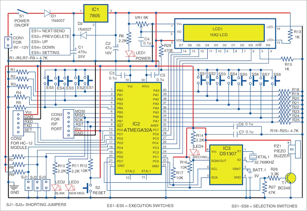
ATmega32A has the required features for this project. It has 32kB flash program memory to store the hex file, 1kB EEPROM to store usernames, 2kB internal SRAM to run the program and hold the values of variables/buffers, two-wire serial interface for RTC IC DS1307 interface, programmable serial USART for HC-12 wireless transceiver, and 32 programmable I/O lines for various switches and other outputs/indicators.
HC-12 is a 5-pin, small-size (28mm ×15mm×4mm approx.) wireless transceiver with antenna. It uses USART port for communicating with the microcontroller (MCU). It has 433.4MHz to 473.0 MHz carrier band with multiple channels to set, with a total of 100 channels with channel stepping of 400kHz, and works on 433.4MHz by default. The maximum transmitting power of the module is 100mW (20dBm). The data sheet indicates that it can communicate up to 1000 metres at 1200 baud rate, and 600 metres at 9600 baud rate (by default), when both transmitter and receiver are placed without any obstruction in between and are visible to each other.
The built-in MCU performs the communication with external device and no programming or configuration is required for basic use of the module. To change any parameters, its SET pin has to be pulled low and AT commands used. By default, the on-board pull-up resistance makes the SET pin high and transmits and receives the wireless data (even without any connection to SET pin).
DS1307 is a popular real time clock (RTC) chip with built-in date and time format and calendar. It uses a 32.768kHz crystal to generate an accurate clock pulse and communicates using a two-wire interface (TWI, also called I2C) with the microcontroller. It has to be powered with 3V battery permanently to run the date and time internally. A 5V DC power supply is required to read or write the date and time from the chip.
Initial setup
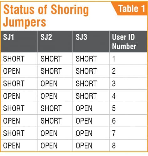
After assembling the circuit on PCB, insert the microcontroller, HC-12 module, and the RTC IC in their respective places. Put the 3V battery in its holder and connect LCD1. Use SJ1, SJ2, and SJ3 shorting jumpers to set an ID number for the board. Switch on power using switch S1 after connecting 9V or 12V DC power supply. Power LED1, seconds LED4, and back-light of LCD1 will start glowing.
Now, write/burn GroupMessenger.hex file into the microcontroller using a suitable AVR programmer through ISP port. Once the program is written to the microcontroller, disconnect the programmer. Use shorting jumpers (refer table) to set ID number for each board. This has to be done only once on initial setup and then left alone.
The program goes through self-test and checks the connections to the external modules. The sequence of testing is as follows with the blinker LED2 blinking for checking every component:
- LCD1 shows ‘Group Messenger’ message for a while.
- The program checks internal EEPROM memory and writes the default usernames in case of new microcontroller. Then reads the saved names from the EEPROM.
- Checks and displays the ID number (1 to 8) and name according to the SJ1 to SJ3 jumper settings.
- The new-message LED3 glows for a while.
- A short beep is heard through the piezo buzzer (PZ1).
- Sets USART for 9600 baud rate and displays the same on LCD1.
- Checks the connections to HC-12 module and displays the Ok/Error message.
- Checks the status of RTC chip and resets to default values, if required. The seconds LED4 starts blinking now, else shows Error message if connections are not proper.
- Enters the main program loop and displays the date and time continuously.
To change your ID name or date and time on first-time use, press ES5 button (Setting). The current username is displayed on LCD1 and cursor blinks for editing the name. Use ES1 (move cursor to next position), ES2 (move cursor to previous position), ES3 (for next ASCII character), and ES4 (for previous ASCII character) for editing the required username. If no button is pressed for more than five seconds, the edited/new username gets saved to EEPROM of the microcontroller. Then the current date and time is displayed on LCD1 along with cursor. Use ES1 (move cursor to next position) and ES3 (increment and loop the number) to set current date and time. If no button is pressed for more than five seconds the edited/current date and time gets saved to the RTC IC DS1307.
At least two such modules (PCBs) are required to send and receive a message in the project. A maximum of eight modules can be used to communicate with each other.
Download source code
Construction and testing
An actual-size PCB layout for the group messenger is shown in Fig. 2 and its components layout in Fig. 3. Assemble the circuit on the PCB. Connect 9V or 12V DC power supply across CON1 and 3V battery across BATT.1. Before inserting MCU into the PCB, do not forget to upload GroupMessenger.hex into it.
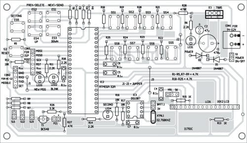
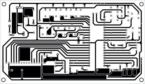
Download PCB and Component Layout PDFs: click here
Use at least two modules for testing; one (Module1) as transmitter and second (Module2) as receiver. The author’s proposed panel for group messenger is shown in Fig. 4.
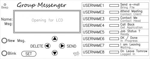
Sending a message
Buttons SS1 through SS8 are selection buttons to select username, first set of the message and second set of the message consecutively. The same eight buttons are used for selecting usernames and two messages assigned to each button. Each button is used for one username and two messages, which are selected by pressing the same button consecutively.
To send a message, first select the username (actual user ID number of SET2 or receiver) by pressing any one of the selection buttons SS1 through SS8. The selected name is displayed on LCD1. Press the same button again to send the required message.
The username and ID are displayed on first row of the LCD. On pressing the same button to select the message (say, Contact me) it appears on second row of the LCD. Now, press ES1 (send button) to send the message. Confirmation of message dispatch will then appear on the LCD followed by time and date.
Data packet format sent by the Module1 is: Ascii27+receiver_id_no +sender_id_no+sender_user_name +space+time+ascii22+the_message_string+ascii26+null
Receiving a message
Module2, which has the user ID_NO selected by Module1 for sending, receives the data, processes it, and displays on the LCD screen continuously until any button (SS1 through SS8 or ES1 through ES5) is pressed by the user. Also, the new-message LED3 glows and a beep is heard whenever a new message is received. Other sets, which do not match the ID_NO, discard the message.
The username and time (in HH:MM format) available in Module1 are also displayed in first row of the LCD in Module2 and the actual received message is displayed in second row of the LCD. The username of Module1 will be saved in the EEPROM (of microcontroller) of Module2. Up to ten such received messages can be saved in each module. But only the latest message received by each module is displayed on the LCD.
To view all the received and stored messages, press ES3 (for next received message) and ES4 (for previous received message) buttons. To delete any message after reading, press ES2 button. On pressing ES3 and ES4 buttons, a small beep is heard if end of messages is reached.
User definitions
The following usernames and messages are defined in the code (GroupMessenger.C). You can change them as per your requirement. Then compile the code using AVR Studio 4 (or above) and write the new GroupMessenger.hex file to the microcontroller.
Usernames
In the below given definition, each username with ten characters (use space if less than ten characters) can be used.
char USER_NAMES[8][11] = { “UserName01”,
“UserName02”,
“UserName03”, “UserName04”,”UserName05”,
“UserName06”, “UserName07”, “UserName08”
};
Messages
The following messages are defined in the code. The length of a message should not exceed sixteen characters, otherwise the message will be truncated in the receiver’s LCD.
char *USER_MESSAGES[] = { “Send e-mail”,
“Attend Meeting”, “Contact Me”, “Call
Back”, “Job Status ?”, “OK / Done”, “I am
Leaving”,”On Leave Tomorrow”, “Bring File”,
“Contact Client”, “Contact Head”,”Get
Application”, “Ready.”, “In Progress…”,
”Waiting…”,”Logged In”};
Notes
- The microcontroller may go to endless loop for reception of acknowledgment from RTC chip on any error or damage, or missing of DS1307.
- The message sent will never be received by receiver module if it is powered off.
- A rechargeable 11.1V, 2200mAH Li-ion battery may be used as power supply.
- The circuit was tested for reception up to 50 metres through walls and slabs and obtained satisfactory results.
Fayaz Hassan is a manager at Visakhapatnam Steel Plant, Visakhapatnam, Andhra Pradesh. His interests include MCU projects, mechatronics and robotics.